
After doing some more research, I decided to jump into configuring my DARwIn-OP’s Dynamixel Teensy 3.2 Driver Prototype to get rid of the retransmitting loop code:
void loop()
{
  if (Serial1.available())
  {
    uint8_t c = Serial1.read();
    Serial1.write(c);
  }
}
This loop just wait for a byte received by the UART and retransmit it with the same UART, which is configured with a hardware direction pin (RTS driven by the transmitter).
If I could use Teensy’s DMA (Direct Memory Access) controller to do the UART retransmission, I could empty the loop so the Teensy can be used in any other tasks without affecting the retransmission performance.
The DMA requirement is very simple:
- To trigger a DMA request when a byte is received by the UART.
- The DMA transfer has to be 1 byte.
- The DMA transfer has to read from the UART DATA register (received data).
- The DMA transfer has to write into the UART DATA register (for retransmission).
- Do not involve the CPU in the process, no interrupt events.
Looking at the DMA capabilities of the Teensy’s ARM MK20DX256VLH7 CPU, it looked feasible, and after a few tries I got it working.
Now the retransmission has a smaller latency and a much smoother timing:
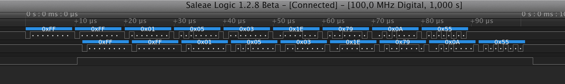
The signals in the chart are:
- RX into the Teensy (from Odroid’s TX).
- TX from the Teensy.
- Hardward Direction Pin.
The coding has a larger setup to configure the DMA and the UART (Teensy’s interrupt driven serial API is no longer useful), but the loop() function is now empty:
#define UART_TXRTSE (2)
#define UART_TXRTSPOL (4)

#define BAUD_RATE (1000000)

void setup()
{
  int divisor = BAUD2DIV(BAUD_RATE);

  // DMA:

  // p 415 source address = uart data register
  DMA_TCD1_SADDR = &UART0_D;

  // p 415 source address offset
  DMA_TCD1_SOFF = 0;

  // p 416 transfer attributes: 8 bits
  DMA_TCD1_ATTR = 0;

  // p 417 minor byte count = 1 byte
  DMA_TCD1_NBYTES_MLNO = 1;

  // p 420 last source address adjustment = 0
  DMA_TCD1_SLAST = 0;

  // p 420 destination address = uart data register
  DMA_TCD1_DADDR = &UART0_D;

  // p 421 destination address offset
  DMA_TCD1_DOFF = 0;

  // p 423 channel link disabled
  DMA_TCD1_CITER_ELINKNO = 1;

  // p 423 last destination address adjustment = 0
  DMA_TCD1_DLASTSGA = 0;

  // p 427 channel link disabled
  DMA_TCD1_BITER_ELINKNO = 1;

  // p 424 control and status = 8 cycle stall, active
  DMA_TCD1_CSR = DMA_TCD_CSR_BWC(3) | DMA_TCD_CSR_ACTIVE;

  // p 402 enable DMA REQ channel 1.
  DMA_SERQ = DMA_SERQ_SERQ(1);

  // clock setup
  // p 252-259 system clock gating
  SIM_SCGC6 |= SIM_SCGC6_DMAMUX;
  SIM_SCGC7 |= SIM_SCGC7_DMA;
  SIM_SCGC4 |= SIM_SCGC4_UART0;

  // wait for clocks to become stable.
  delay(500);

  // p366 dma mux channel configuration
  DMAMUX0_CHCFG1 = DMAMUX_ENABLE | DMAMUX_SOURCE_UART0_RX;

  // UART:

  // p 1222 UART0 Control Register 5 request DMA on receiver full
  UART0_C5 = UART_C5_RDMAS;

  // RX TX pins
  CORE_PIN0_CONFIG = PORT_PCR_PE | PORT_PCR_PS |
                     PORT_PCR_PFE | PORT_PCR_MUX(3);

  CORE_PIN1_CONFIG = PORT_PCR_DSE | PORT_PCR_SRE |
                     PORT_PCR_MUX(3);

  // p 1208 uart0 baud rate
  UART0_BDH = (divisor >> 13) & 0x1F;
  UART0_BDL = (divisor >> 5) & 0xFF;
  UART0_C4 = divisor & 0x1F;

  UART0_C1 = UART_C1_ILT;
  UART0_TWFIFO = 2; // tx watermark
  UART0_RWFIFO = 1; // rx watermark
  UART0_PFIFO = UART_PFIFO_TXFE | UART_PFIFO_RXFE;

  UART0_C2 = UART_C2_TE | UART_C2_RE | UART_C2_RIE;

  // enable PIN 6 as hardware transmitter RTS with active HIGH.
  CORE_PIN6_CONFIG = PORT_PCR_MUX(3);
  UART0_MODEM = UART_TXRTSE | UART_TXRTSPOL;
}

void loop()
{
}
Actually, now I am running the typical ‘blink’ in the loop() function just so I know the Teensy is running.