First Leg finished for my DARwIn-OP Robot Clone

Now that I finished the Flange Bearings and Bearing Idlers, I am doing a test of the full assembly of the first leg of my DARwIn-OP clone.

DARwIn-OP's Fully Assembled Leg
DARwIn-OP’s Fully Assembled Leg

After adjusting the bends of the FR07_H120 frames the idlers align perfectly.

Flange and Idler installed

Now I’ll continue making the rest of the HR07_I101 Bearing Idlers (still 9 to go) before starting to bend the frames for the second leg and start cutting the frames from the waist up. Anyway I am still waiting for some black dye to arrive before anodizing the frames.

Cutting Flange Bearings for my DARwIn-OP robot clone

I almost decided to buy the 4 Flange Bearings FR07_F101 needed for a DARwIn-OP clone. But it just took me one afternoon to cut them on the lathe and drill them on a mill.

Finishing a FR07_F101
Four FR07_F101
Four FR07_F101

I tested the assembly of a bearing joint as described in the DARwIn-OP Assembly Manual. I haven’t anodize the parts and it seems  I’ll have a hard time disassembling the joint, the bearing is very tight.

Bearing Joint Assembled

The gcode cut programs are in the Code Section and zipped in File Section in sourceforge repository for cloning the DARwIn-OP Robot.

Now I can continue testing the full assembly of a leg of my DARwIn-OP clone.

DARwIn-OP Robot Clone Bearing Idler

Just got the MF106ZZ ball bearings and some 6061 aluminum bars for my DARwIn-OP robot clone.

Ball Bearings
MF106FF Ball Bearings

I cut a bunch of HN07-I101, and RX28-CAP on my lathe as in my test cuts. I devised a tool to hold the HN07-I101 and FR07-F101 while drilling the missing eight 1.6mm hole pattern.

Holding Tool with Blank HR07-I101 and Original HR07-I101 on right

The hole pattern is drilled on a Sherline Mill using a #1 center drill and a 1.6mm drill.

Drilling Hole Pattern on HR07-I101

Finally the HR07-I101 Bearing Idler has to be tapped to M2.

Finished HR07-I101 on left and HR07-I101 original on right

Updated: The gcode cut programs are in the Code Section and zipped in File Section in sourceforge repository for cloning the DARwIn-OP Robot. The tool is machined on a lathe and finished on a mill for the 4 clamping screws.

Finished with the Lathe Cuts

At last I finished cutting all HR07-I101 parts, with a few spares. So I am finished with the lathe cuts. The DARwIn-OP robot clone requires 15 HR07-I101s, 15 RX28-CAPs, and 4 FR07-F101. I thought about buying all these parts but making them wasn’t so bad, specially with the lathe’s quick-change tools it is easy to make identical parts. Tapping all the 2mm threads was a bit tedious.

Bunch of HR07-I101
Bunch of HR07-I101

Now I will polish and try to anodize the HR07-I101s and RX28-CAPs with natural aluminum finish (all other parts should be black anodized, still waiting for the black dye) before mounting.

CNC Sherline Mill Extended Table Upgrade

I decided to upgrade my Sherline Mill. I got an extended 19″ X axis table from A2Z and a 14″ matrix plate from High Tech Systems. Sherline also has an extended table, but I wanted to try this brand because it is a little more taller and milling frames for a DARwIn-OP robot clone is a very low profile work and the endmills used are too short. The matrix table helps in height and supporting a 4″ wide work.

Extended Table and Matrix Plate

The matrix plate is quite nice, just one corner got scratched, probably on the trip to Chile. The extended table is quite long. To install it requires to adjust the gib on the base dovetail which took me hours, now I have a 360mm range on the X axis.

I drilled a new pattern of holes in the matrix plate to better hold aluminum plates for cutting DARwIn-OP’s frames.

New Hole Pattern
New Hole Pattern

The hole pattern has M2.5 threads. The holes are ½” apart to align to the preexisting pattern. I made 3 hole lines, one at the middle and one at 5/32″ from each border of the 4″ plate.

DARwIn-OP robot

And so it goes, I was reviewing for some time which robotics platform I could buy or build to get my hands dirty.

As I started looking at models in the few hundred dollar range as a base for development, I soon moved into looking at the over a thousand dollar humanoid range specs. But the lack of higher imaging and processing capabilities made me continue looking into higher and quite unaffordable ranges… Just looking…

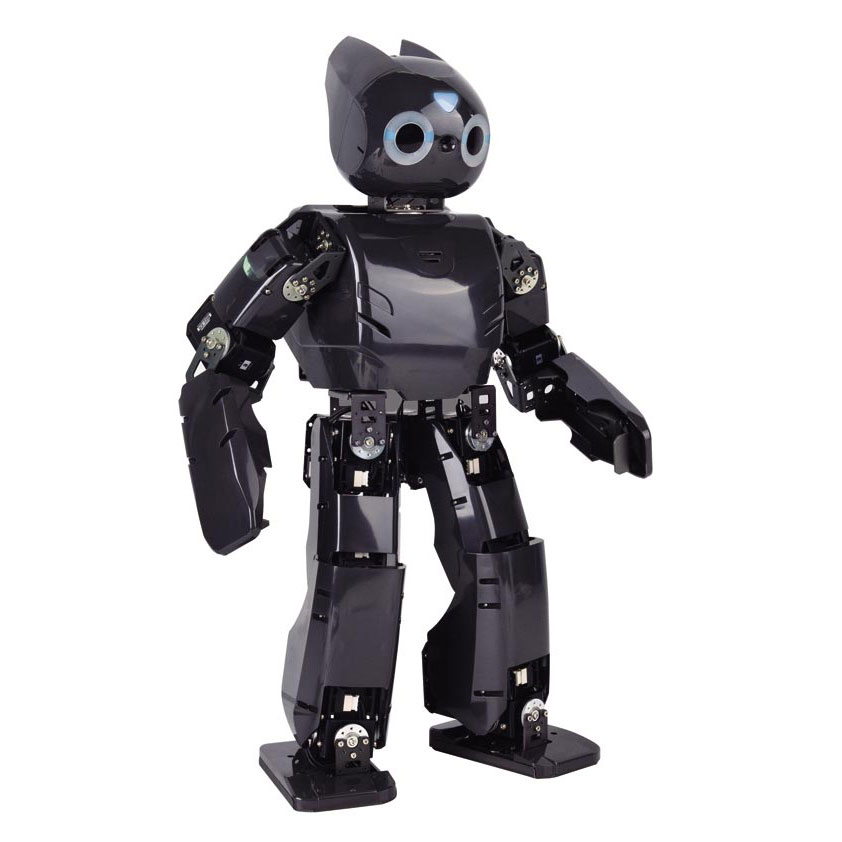
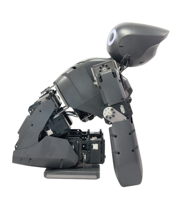
And then I stumble with DARwIn-OP platform which was developed by the robot manufacturer Robotis in collaboration with Virginia Tech, Purdue University, and University of Pennsylvania.

DARwIn-OPDARwIN-OP-kneelback

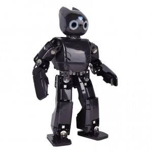
It is an open source humanoid platform with an on-board PC running Linux (Ubuntu) with good enough power, network capabilities, and even an on-board Webcam for image processing. The robot is not cheap at 12,000 USD. But it is open source and by that I mean:

  • The mechanical specs and designs are open source and published online in sourceforge.
  • The Fabrication and Assembly Manuals are also published online with the specs.
  • And also the Control Software source code is open source and published, even the ISOs with Ubuntu and the software installed.

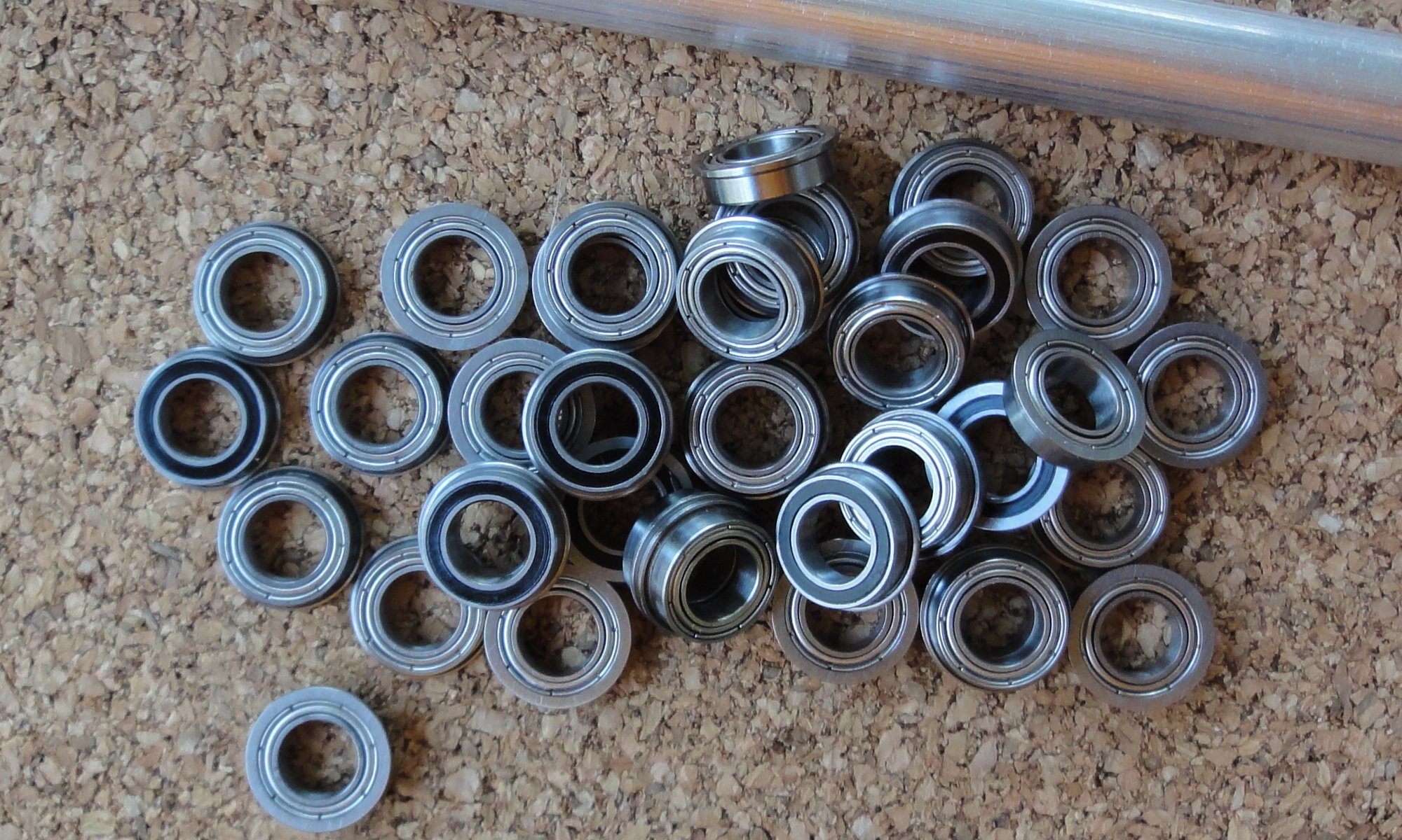
So you can make a DARwIn-OP robot clone. You still need to buy the servos (20 minimum) and the electronics. But it was designed to be cloned.

The robot is not too new, the University of Pennsylvania has won the RoboCup’s kid-size league for the last 3 years with a DARwIn-OP team. It has been used in many Universities. Also, there is a DARwIn-OP clone under development using 3D printing at about half the cost, you can read Michael Overstreet’s blog. Simulators are also available. It is programmed in C++ and a few upgrades are available like feet with pressure sensors and gripper arms.

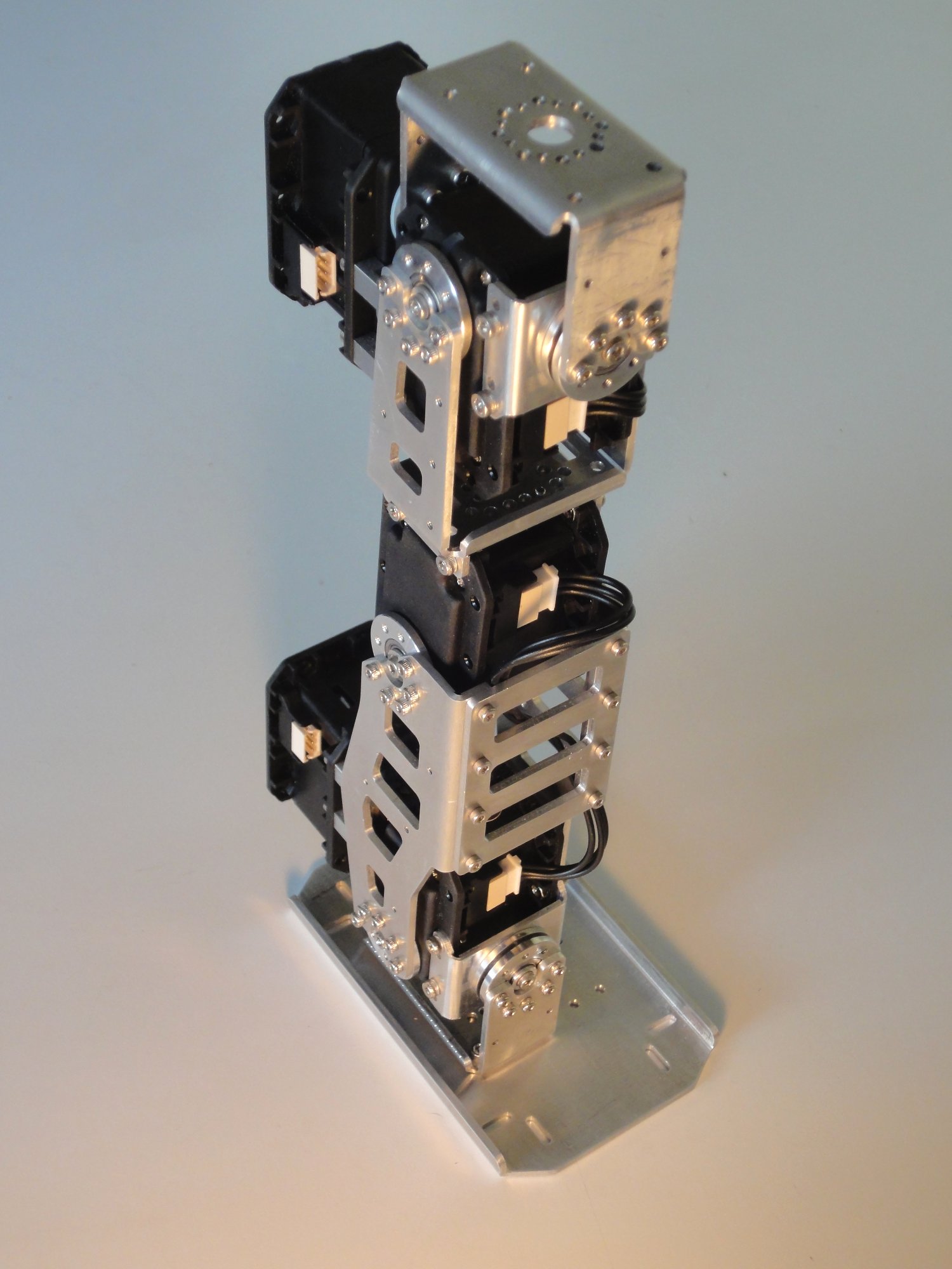
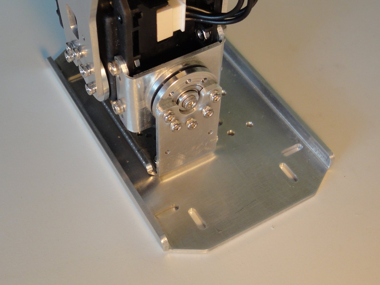
So I gathered enough arguments to convince myself to make a DARwIn-OP clone (of course I minimized aspects like the cost of its sophisticated and expensive Dynamixel MX-28T servos which have to be bought, 20 of them… but that can be stretched as the building process takes place).

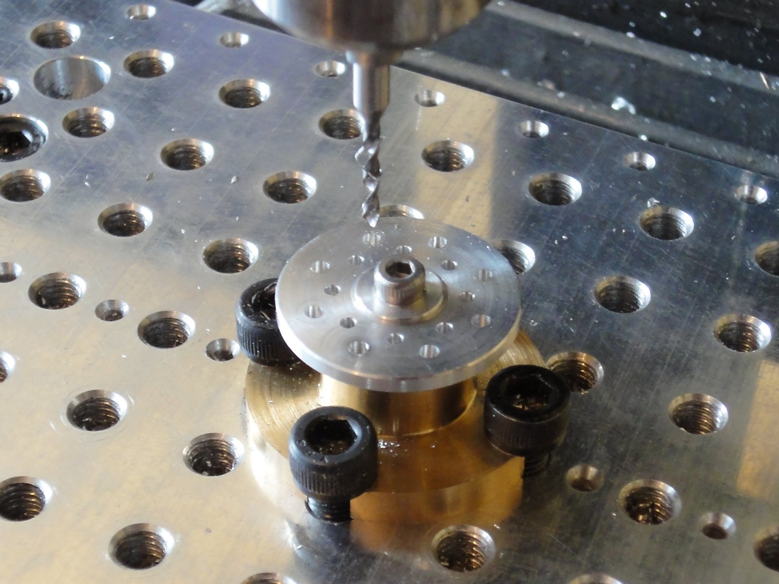
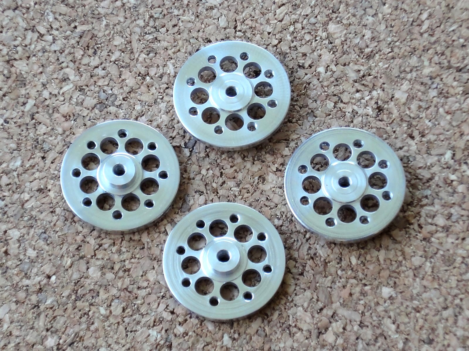
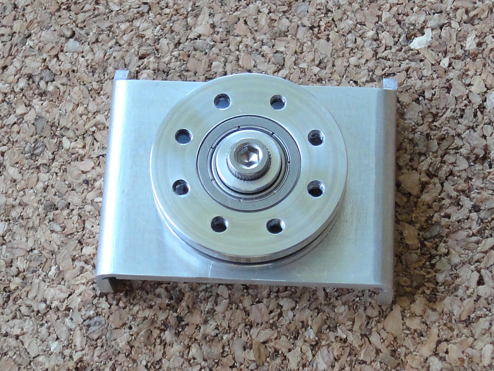
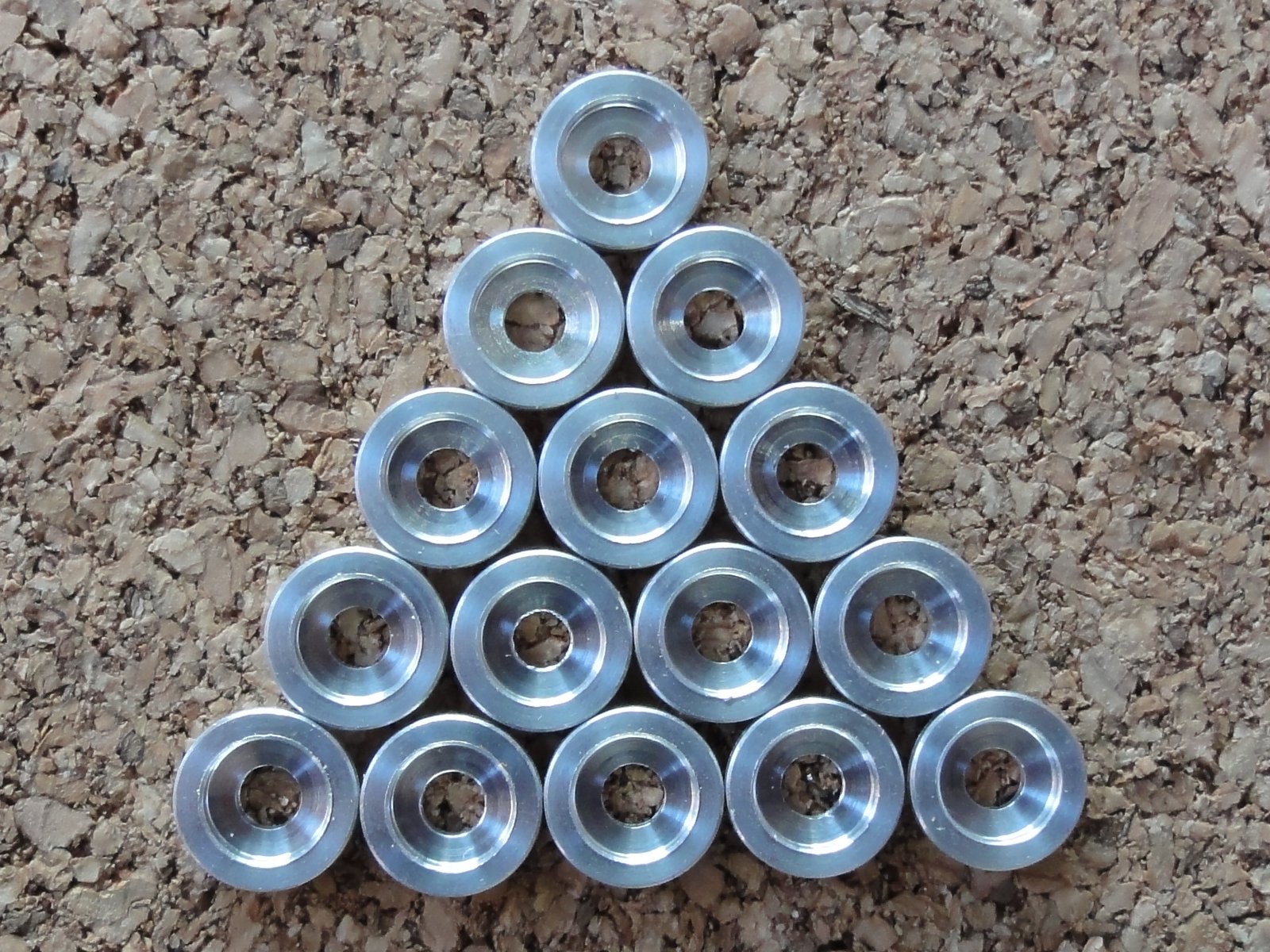
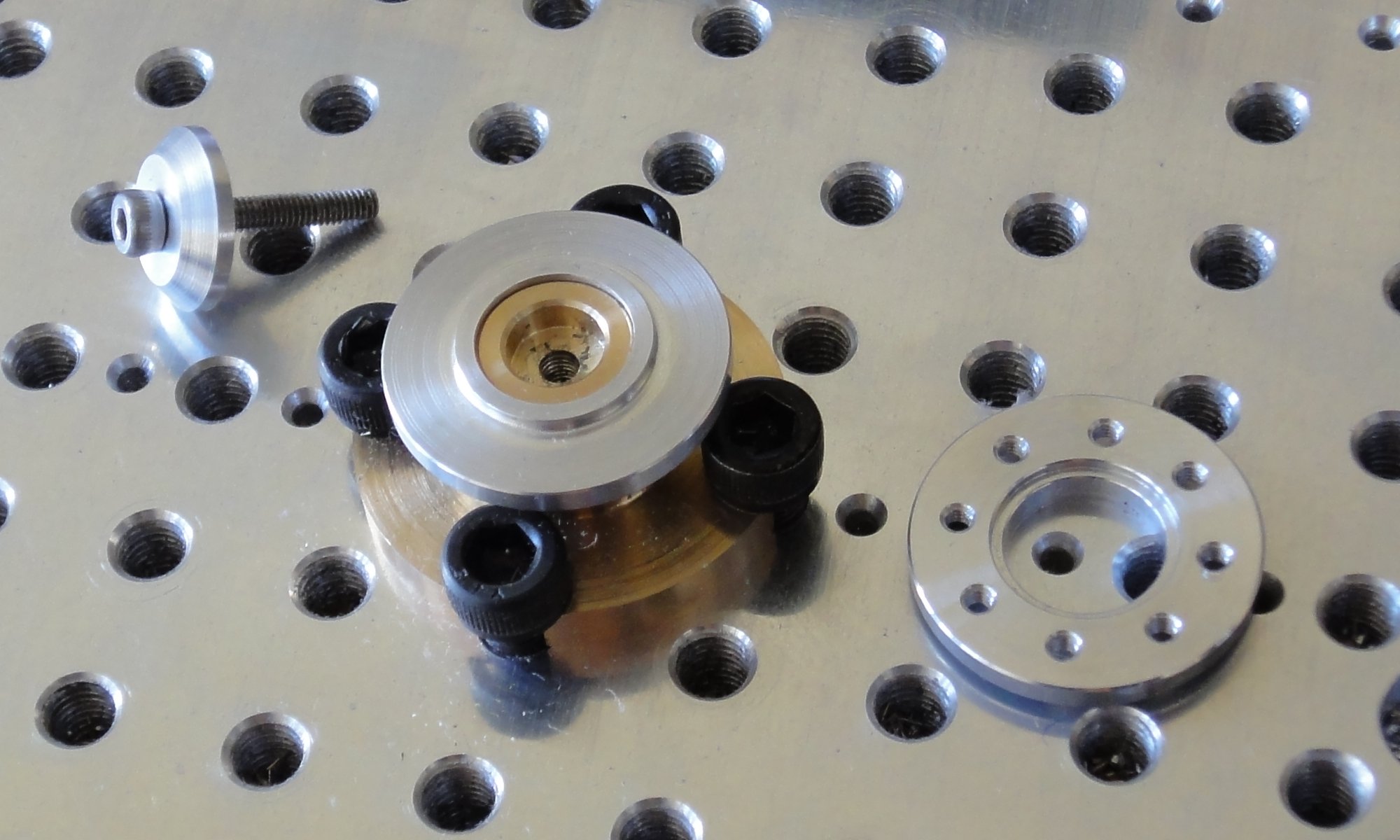
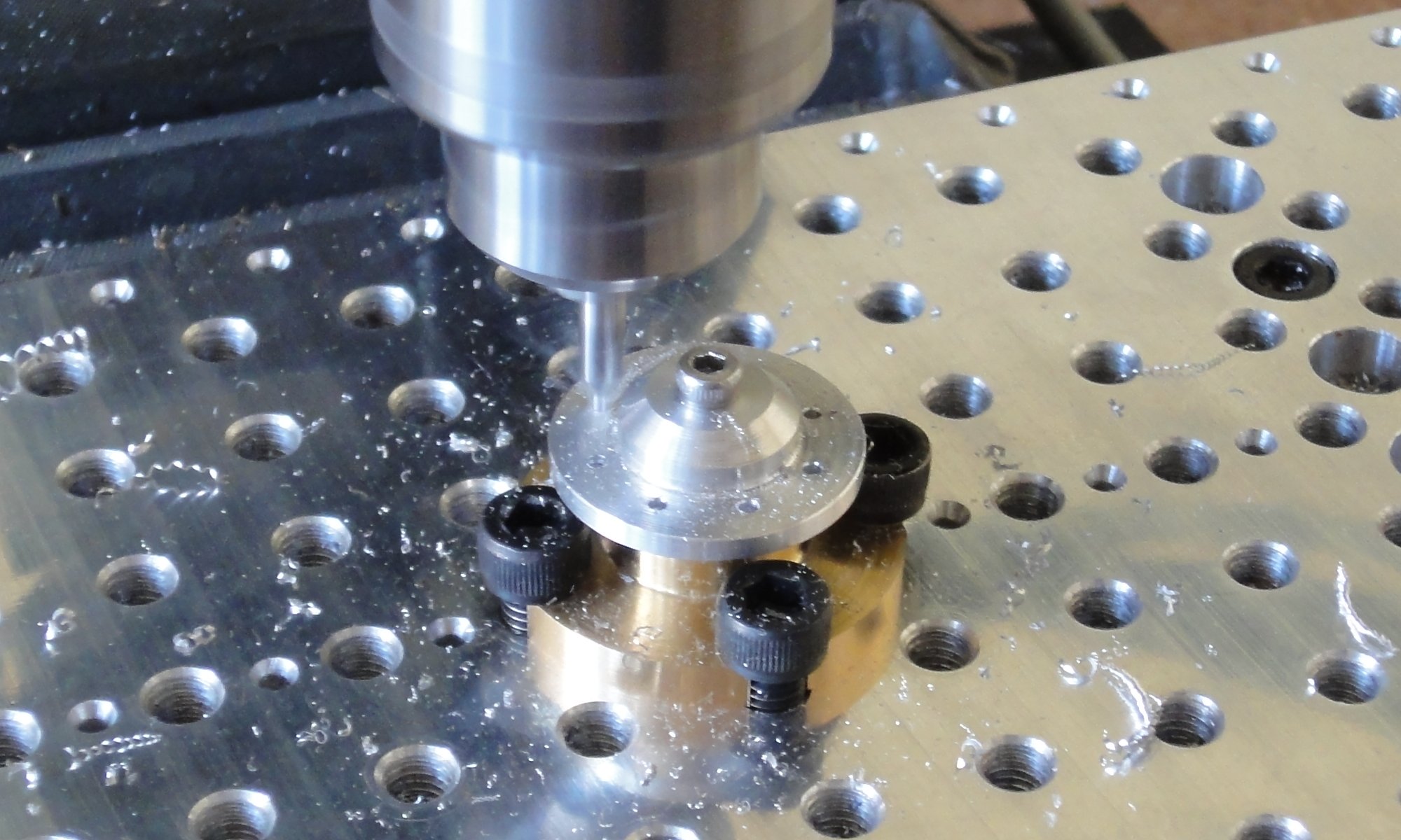
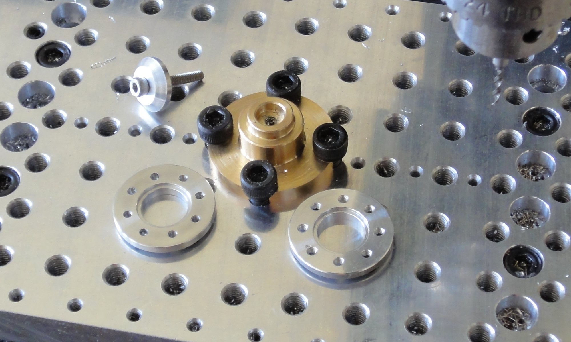
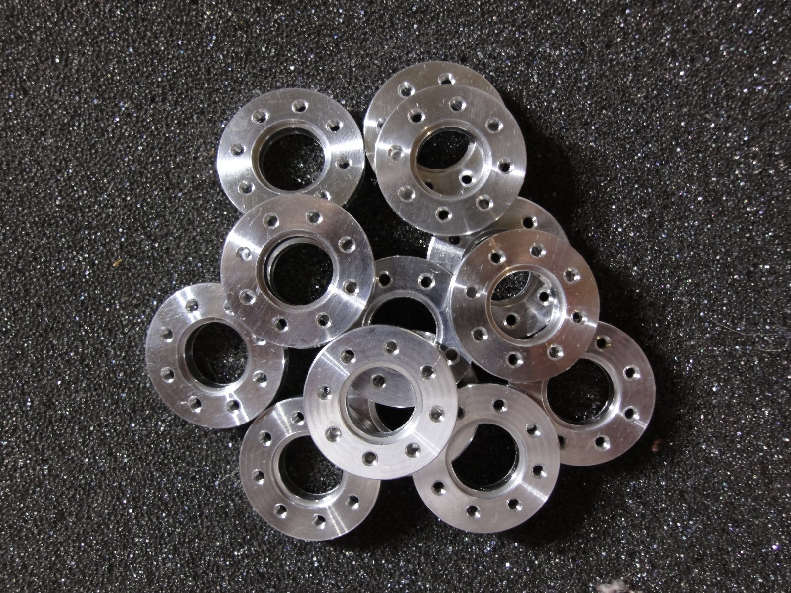
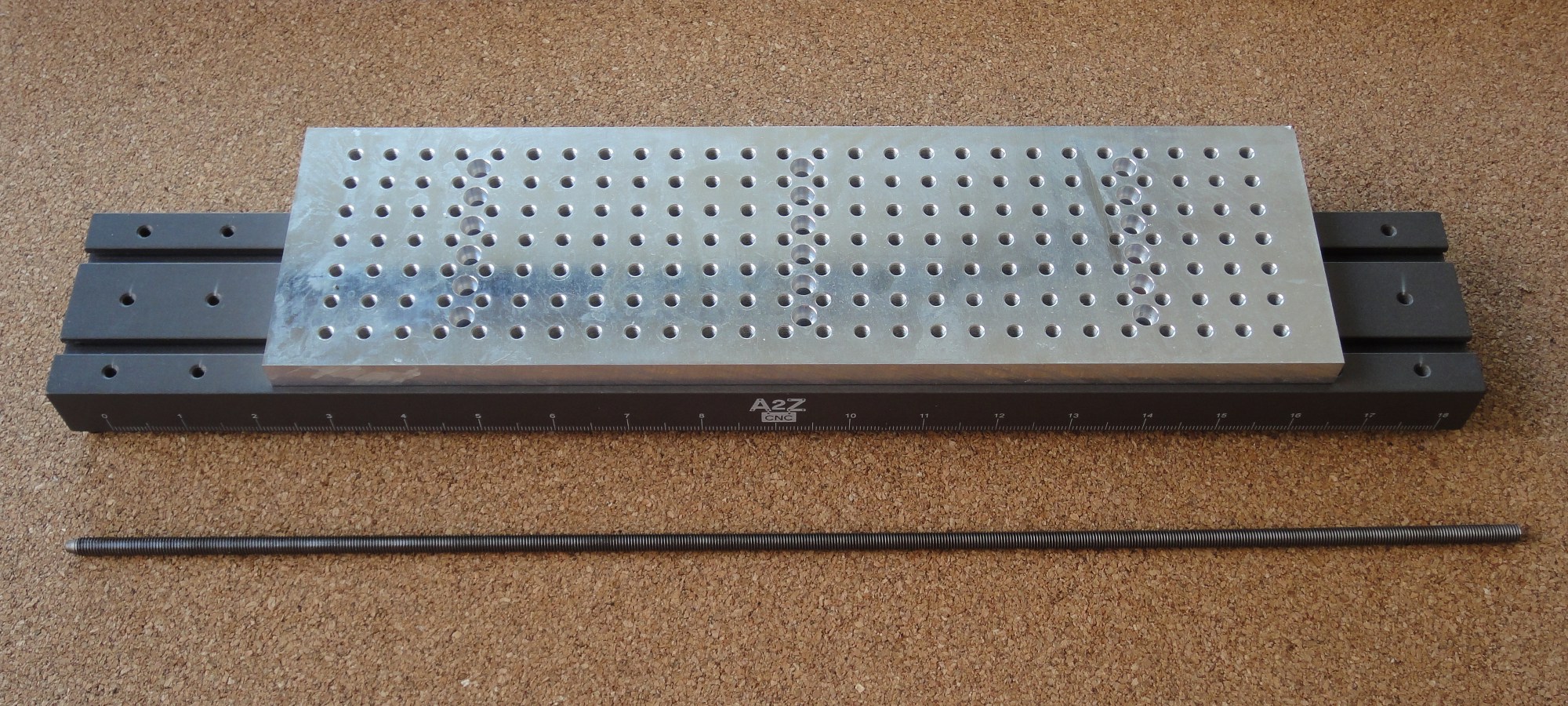
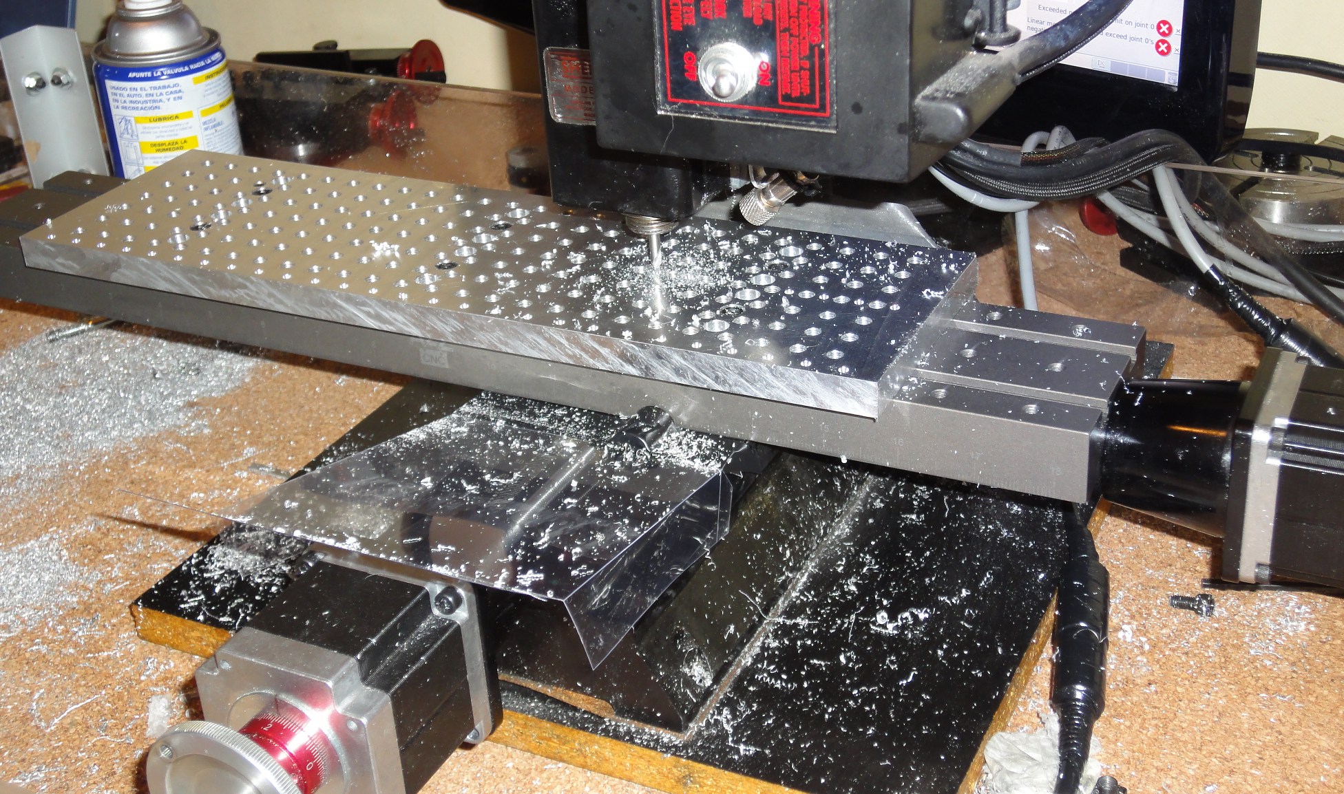
I intend to make the structural frame from aluminum as original designed, using hobbyist CNC tools. I’ll leave 3D printing for the external plastic covers. For the electronics, I’ll later decide if I’ll use the original Atom motherboard or I’ll do an upgrade to a more powerful one, maybe with an ARM cpu, the Cortex-A15 should soon be available in a usable motherboard size. I decided not to replace the servos with a cheaper alternative, there are too many variables already floating around to add more complexity.