Now that the first proof of concept was done with the first test cut, I am continuing with the DARwIn-OP frame parts bottom up starting with one leg.
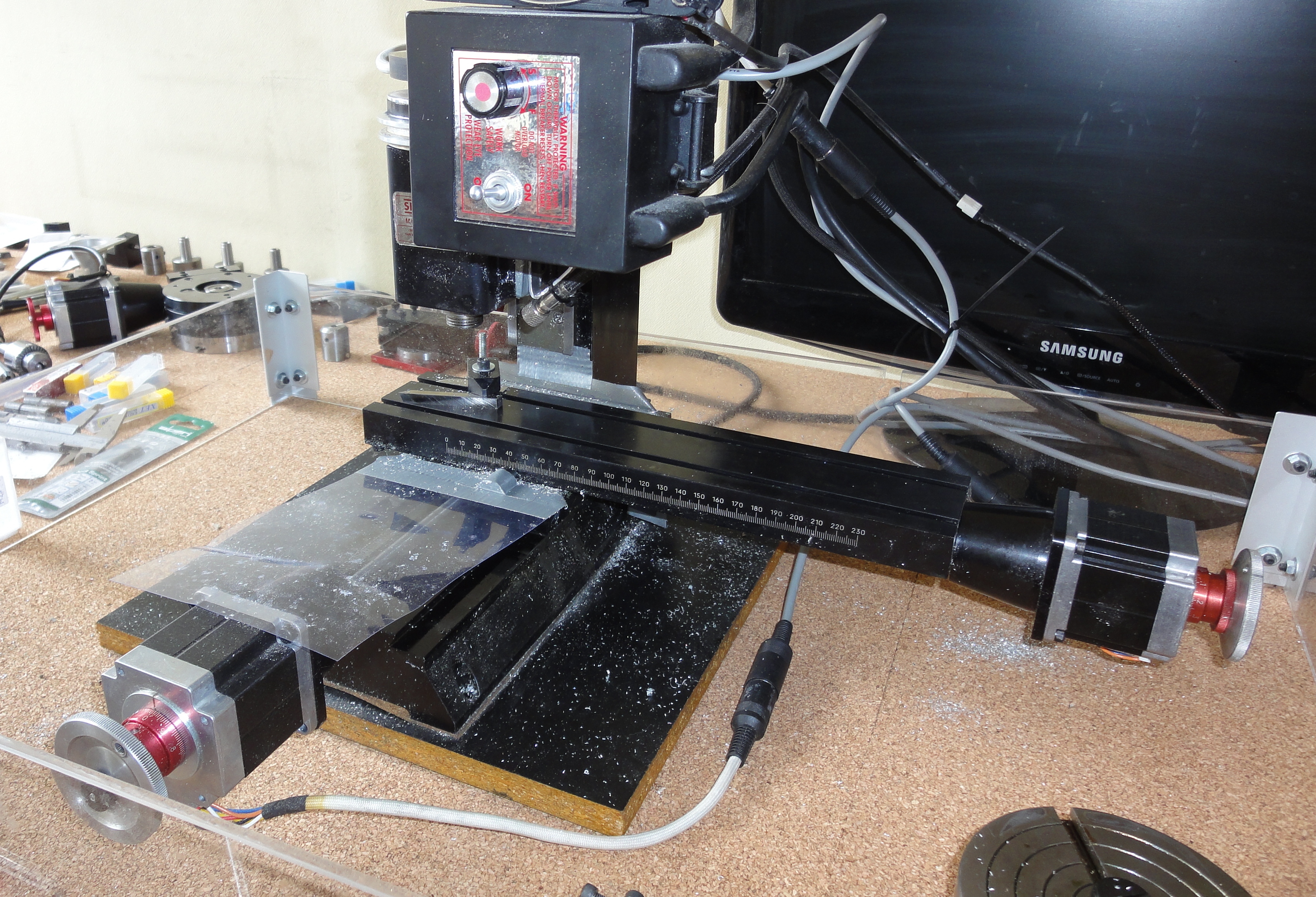
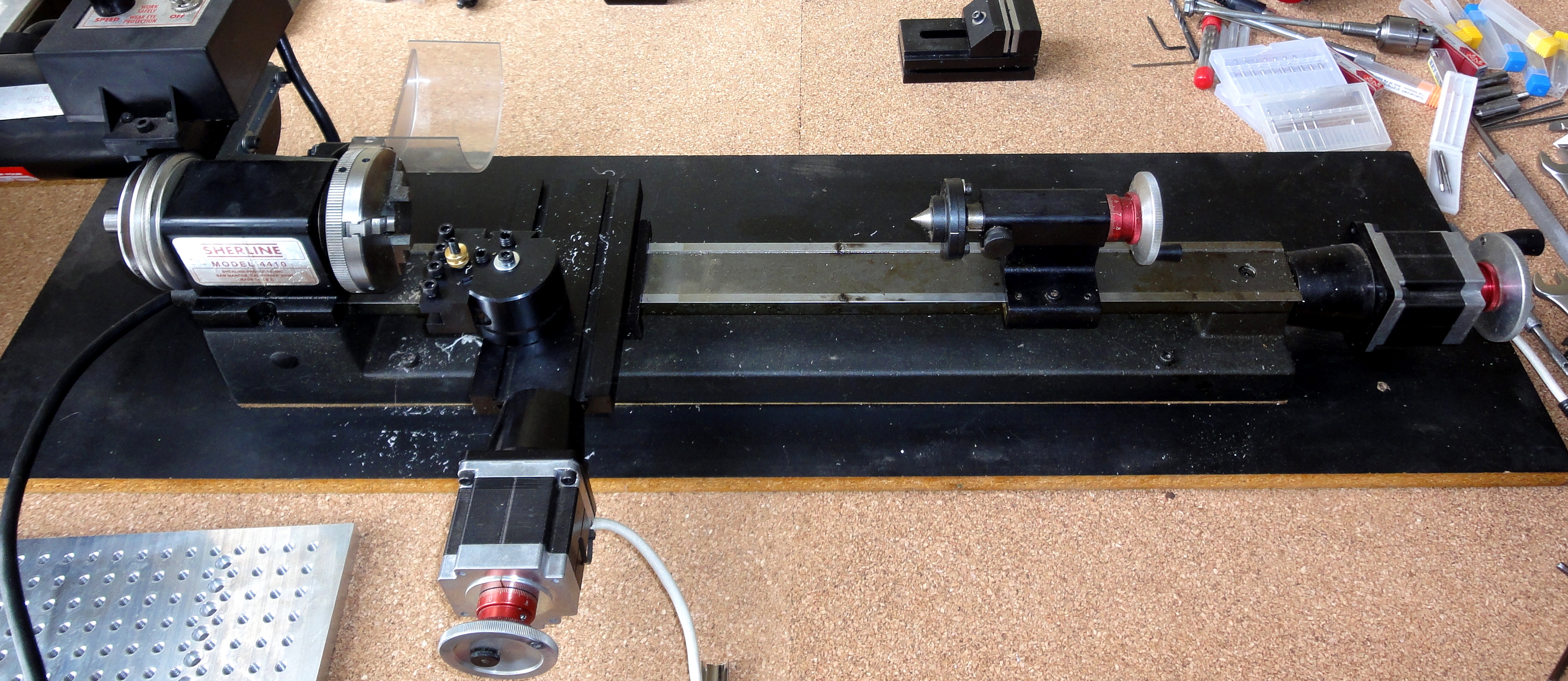
Since my Sherline mill can manage a surface about 200x100mm. I sliced out my aluminum sheets in smaller pieces, after the first few cuts I ended up reducing the size to 150x100mm and 200x100mm pieces depending on the size of the parts to cut.
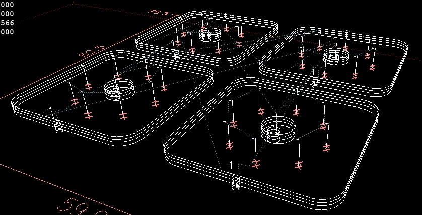
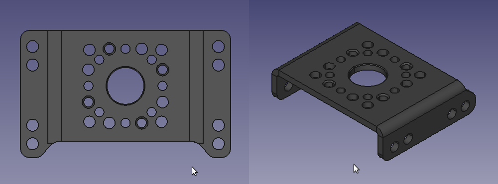
The foot is the FR07_E160 frame. The Fabrication Manual lists this part as 1.5mm thick on page 8. But the 2D and 3D model files are consistent with a 2mm thick part. I believe the manual is the one mistaken.
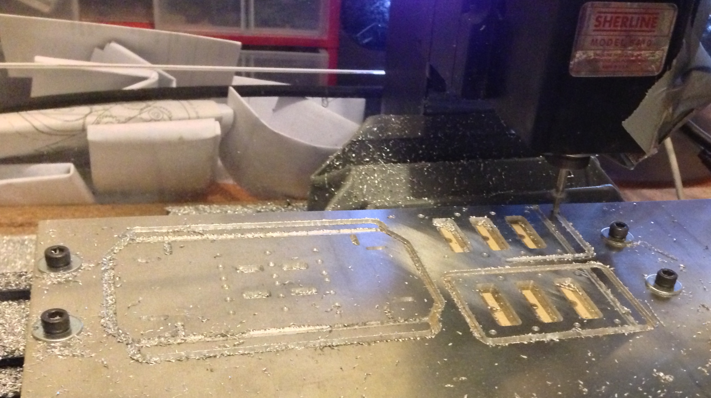
The first foot was cut over a 9mm wood plate. I later changed to using an 1/4″ aluminum plate as this is much more sturdy, I’ll go on this latter. The tools used are:
- Centerdrill #1
- drill 2mm (since at the moment I didn’t have a 2.05mm drill yet, the holes must all be 2.5mm tapped).
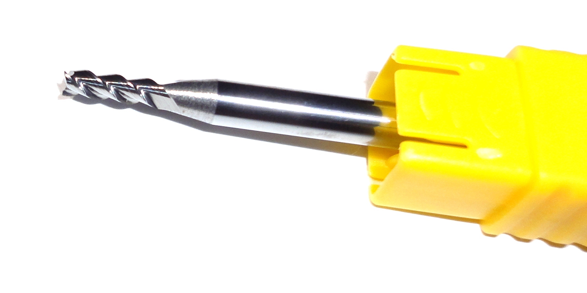
- endmill 2.5mm for the slots (the thinner ones mesure 2.6mm wide on the model).
- endmill 3mm for the cut-off. I latter stopped using the 3mm endmill as this requires an extra tool change (My mill does not a fancy automatic tool change).
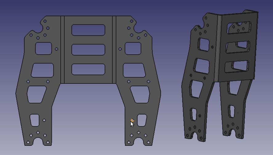
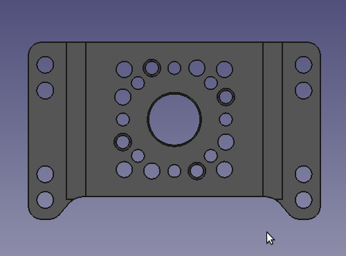
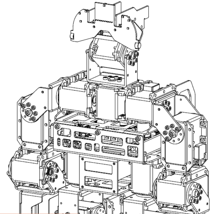
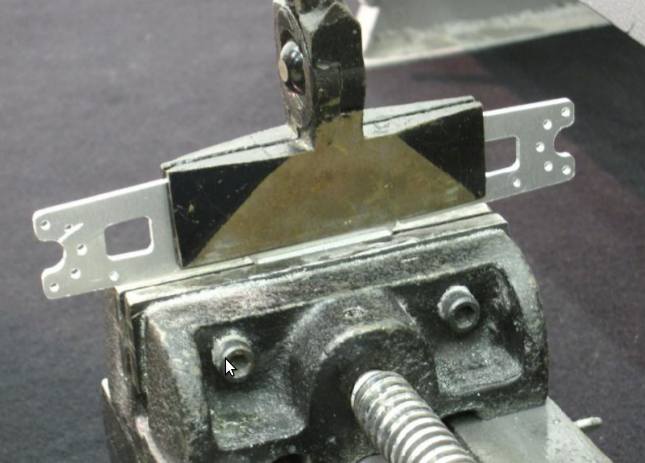
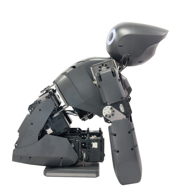
With the foot I also cut a couple of ‘knees’. The DARwIn-OP may seem to be a small robot in pictures, considering it is about 45cm high (1.5 feet). But some frame parts are not as small as I imagined initially. The lower leg part FR07_H133 is about 118x106mm before bending. Considering also the endmill width, the mill is short in about 10 millimeters in its shorter Y axis.