Periféricos del clon de DARwIn-OP

El robot original DARwIn-OP usa un computador Intel Atom Z530 de 1.6 GHz y un controlador ARM CM-730. Este controlador incluye un giroscopio de 3 ejes, un acelerómetro de 3 ejes y un bus Dynamixel para conectar los servos del robot.

Por mi parte, pretendo usar una electrónica alternativa basada en un computador ARM más poderoso (y barato). Para el computador principal, mi candidato es el ODROID-XU que es un quad Cortex-A15 1.6GHz con 2GB de RAM.

En vez del controlador, usaré un USB2AX para conectar los servos Dynamixel y varios componentes I2C para el giroscopio y acelerómetro.

odroidxu-peripherals
ODROID-XU y periféricos

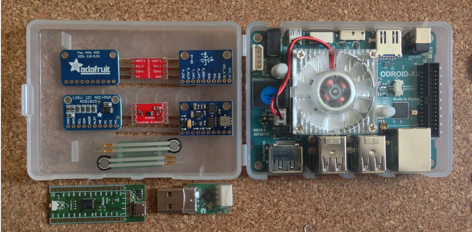
En la imagen se muestran los componentes que ya tengo que estaré probando:

  • Conversor ADC I2C de 12 bit y 4 canales (chip ADS1015)
  • Traductor de voltaje I2C (chip PCA9306)
  • un multi componente I2C 10DOF con sensores de giroscopio de 3 ejes, acelerómetro de 3 ejes, compás de 3 ejes, temperaura y presión (chips, L3G4200D, ADXL345, HMC5883L, BMP085)
  • Resistencia sensora de fuerza (.1N to 100N)
  • USB IO Board para ODROID con interfaces de GPIO/PWM/SPI/UART/I2C/ADC
  • Interfaz Dynamixel USB2AX

Usaré el bus I2C nativo I2C_0 que se encuentra en el conector LCD (CON15) en la parte inferior del ODROID-XU (el esquemático está disponible en Hardkernel vía petición por email).

ODROID-XU LCD connector and cable
conector LCD del ODROID-XU y cable

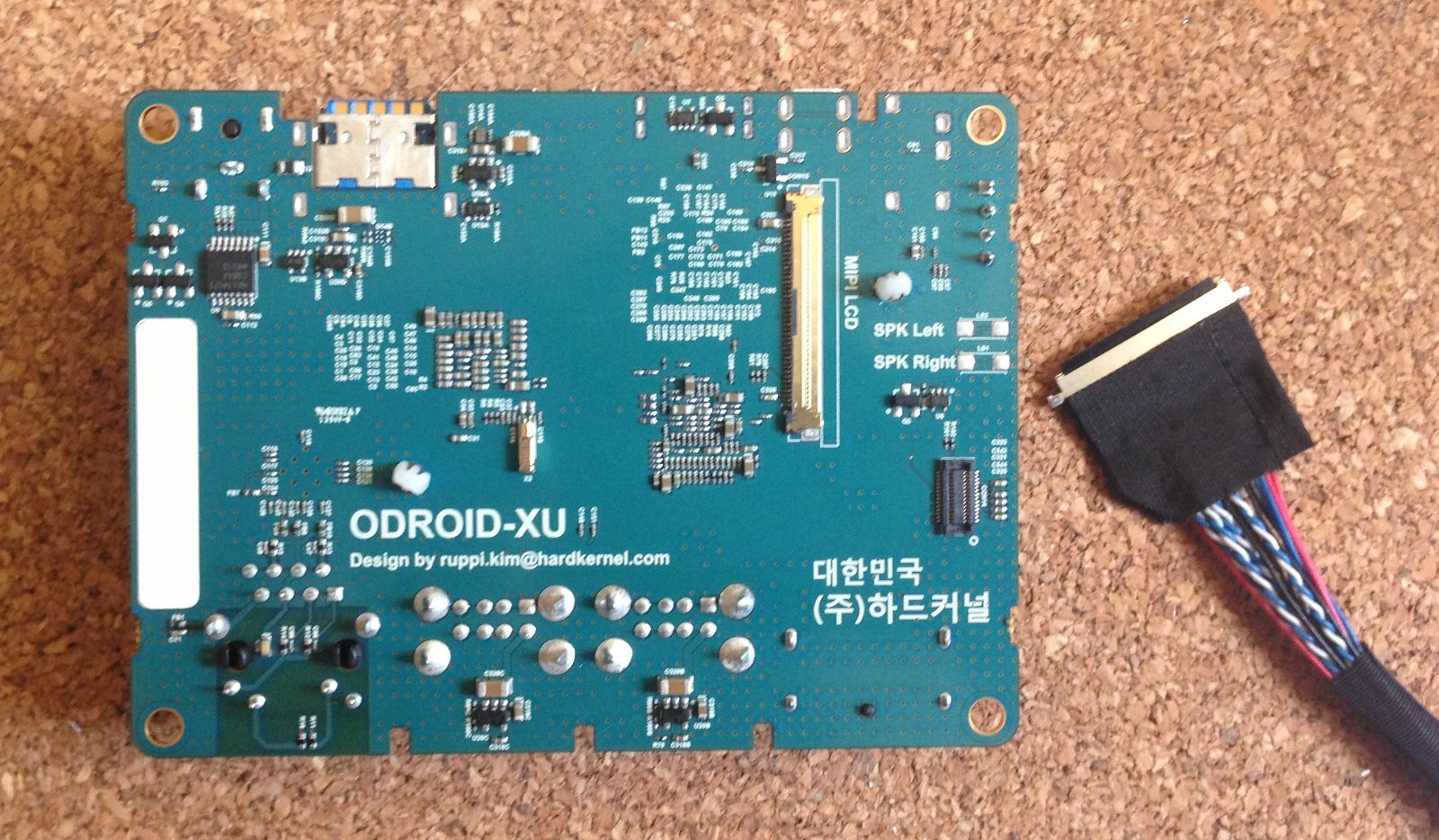
El conector LCD es un IPEX de 40 pines de 0.5mm. Compré un par de cables en Ebay, aunque ahora noté que Hardkernel (el fabricante de ODROID) lo ofrece a la venta también. La configuración de pines que usaré para la interfaz I2C es:

  • 4 – 1.8V
  • 6 – SCL
  • 7 – SDA
  • 10 – GND

La interfaz I2C del ODROID-XU es de 1.8V, por lo que el PCA9306 servirá para interconectar el resto de los componentes I2C que son de mayor voltaje.

El DARwIn-OP requiere un giroscopio y acelerómetro, pero me interesa usar el compás y los sensores de fuerza (vía los conversores AD) para una futura versión de los pies del DARwIn-OP.

DARwIn-OP Clone Peripherals

The original DARwIn-OP Robot uses an on-board 1.6 GHz Intel Atom Z530 computer and a CM-730 ARM controller board. This controller board includes a 3-axis gyro, a 3-axis accelerometer and a Dynamixel bus to interface with the robot’s servos.

I intend to use an alternative electronics based on a more powerful ARM computer plus several peripherals. For the main computer, my current choice is the ODROID-XU which is a quad Cortex-A15 1.6GHz CPU with 2GB RAM.

Instead of using a controller board, I’ll be using a USB2AX to interface the Dynamixel servos and I’ll use I2C components for the gyroscope and accelerometer.

odroidxu-peripherals
ODROID-XU and peripherals

On the picture are shown the components that I already got and that I’ll be testing:

  • I2C 12 bit 4 channels ADC (ADS1015 chip)
  • I2C voltage-level translator (PCA9306 chip)
  • I2C 10DOF with 3-axis gyro, 3-axis accelerometer, 3-axis compass, temperature and pressure sensors (L3G4200D, ADXL345, HMC5883L, BMP085 chips)
  • Force sensing resistor (.1N to 100N)
  • ODROID USB IO Board with GPIO/PWM/SPI/UART/I2C/ADC interfaces
  • USB2AX Dynamixel interface

I’ll be using the native I2C interface I2C_0 that is available in the LCD connector (CON15) in the back of the ODROID-XU (the schematics are available through a customer email request to Hardkernel).

ODROID-XU LCD connector and cable

The LCD connector is an IPEX 40 pin with 0.5mm pitch. I got some a couple of cables from Ebay, but now I saw that Hardkernel (the maker of the ODROID) is also selling the cable. The pin configuration that I’ll be using for the I2C interface is:

  • 4 – 1.8V
  • 6 – SCL
  • 7 – SDA
  • 10 – GND

The ODROID-XU’s I2C interface is rated at 1.8V, so I’ll be using the PCA9306 to translate it to the rest of the I2C components which are rated at a higher voltage.

The DARwIn-OP requires a gyroscope and an accelerometer, but I am interested also in using the compass and the force sensors (through the AD converter) for a future version of the DARwIn-OP feet.

Pausa

Después de 6 meses de pausa, estoy retomando mi proyecto de construir un clon del robot DARwIn-OP.

El primer paso es corregir un error con un plugin multi-lenguaje de WordPress que estaba produciendo problemas con los posts en español e inglés desde hace un tiempo.

Pause

After a 6 month idle period, I am retaking my project to build a DARwIn-OP robot clone.

The first order of business was to fix an issue with a WordPress multi-language plugin that was screwing up the blog in English and Spanish for some time now.

Primer Lote de Anodizado para mi Clon de DARwIn-OP

Después de hacer algunas pruebas, terminé con las ruedas volantes anodizadas, todavía estoy esperando que llegue tintura negra, pero estas ruedas volantes son color natural.

Anodized Idler
Rueda Volante Anodizada

El procedimiento usado es:

  1. Pulir las piezas
  2. Lavar las piezas y enjuagarlas en agua destilada.
  3. Baño de 1 minuto en hidróxido de sodio (10g/L).
  4. Anodizado Tipo II por 60 minutos: 12A/Ft² con ácido sulfúrico al 15% (ácido de matería diluido 50/50 con agua destilada) a 20°C.
  5. Hervir por 30 minutos en agua destilada.

Como hice algunas pruebas de piezas con aluminio 2011, las usé para probar el anodizado primero. La terminación de la superficie depende de la aleación usada. Con aluminio 6061 obtuve una mejor terminación.

Anodized Aluminum 6061 on top, Aluminum 2011 prototype on bottom
Pieza de Aluminio 6061 Anodizado arriba, prototipo de Aluminio 2011 abajo
Preparing an anodizing batch
Preparando un Lote para Anodizar

Obtuve algunas piezas con marcas de anodizado, en especial unas pocas tapas de rodamiento. Por lo menos tengo algunas sobrantes y son fáciles de hacer. Vi un tutorial en YouTube en que enfatizan que las piezas nunca están suficientemente limpias para anodizar. De todas formas, necesito investigar y probar más antes de anodizar y teñir el resto de las partes del DARwIn-OP.

Failed Anodize Cap Example
Ejemplo Falla en Anodizado de Tapa de Rodamiento

También voy a probar con un baño de hidróxido de sodio más largo, el engrosamiento de las piezas por la capa de anodizado es notoria ya que los rodamientos quedan más ajustados, así que hay espacio para un baño más largo (que carcome un poco de la superficie).

First Anodizing Batch for my DARwIn-OP Clone

After doing some tests, I finished with all Idlers anodized. I am still waiting for some black dye to arrive, but the Idlers and Caps don’t use dye.

Anodized Idler
Anodized Idler and Cap Mounted

The process used was:

  1. Polish the parts.
  2. Wash the parts with soap and rinse in distilled water.
  3. 1 minute bath in sodium hydroxide (10g/L).
  4. 60 minutes of Type II anodizing: 12A/Ft² with 15% sulfuric acid (battery acid diluted 50/50 with distilled water) at 20°C.
  5. 30 minutes boiled in distilled water.

Since I did my first test cuts with some aluminum 2011, I used this test Idlers to try the anodizing process first. The surface finish will depend on the aluminum alloy used. With the 6061 alloy I got a nicer finish.

Anodized Aluminum 6061 on top, Aluminum 2011 prototype on bottom
Preparing an anodizing batch

I did get some parts ruined with some anodizing marks, specially in a few Idler Caps. At least I have a few spares and they are easy to make. I saw in a tutorial video in YouTube that the parts are never clean enough to anodize them. Anyway, I need to do more research and tests before anodizing and dyeing the frames.

Failed Anodize Cap Example
Failed Anodized Cap Example

I will also test using a longer sodium hydroxide bath. The aluminum oxide buildup by anodizing is noticeable since the ball bearing fits tighter in the Idler, there is space for a longer bath (since it eats up some material).

Primera Pierna Terminada para mi Clon de Robot DARwIn-OP

Ahora que terminé los FR07_F101 (Flange Bearings) y algunos HN07_I101 (Bearing Idlers), estoy haciendo una prueba de ensamblado completa de la primera pierna de mi clon de DARwIn-OP.

DARwIn-OP's Fully Assembled Leg
Ensamblado de una pierna completa de DARwIn-OP

Después de ajustar los pliegues de las piezas FR07_H120, las ruedas volantes alinean perfectamente.

Flange and Idler installed
Rueda volante instalada

Ahora voy a continuar fabricando el resto de los HR07_I101 (Bearing Idlers, me faltan 9 todavía) antes de empezar a plegar las piezas de la segunda pierna y seguir con la cintura para arriba. De todas maneras estoy esperando tinta negra para anodizar las piezas.

First Leg finished for my DARwIn-OP Robot Clone

Now that I finished the Flange Bearings and Bearing Idlers, I am doing a test of the full assembly of the first leg of my DARwIn-OP clone.

DARwIn-OP's Fully Assembled Leg
DARwIn-OP’s Fully Assembled Leg

After adjusting the bends of the FR07_H120 frames the idlers align perfectly.

Flange and Idler installed

Now I’ll continue making the rest of the HR07_I101 Bearing Idlers (still 9 to go) before starting to bend the frames for the second leg and start cutting the frames from the waist up. Anyway I am still waiting for some black dye to arrive before anodizing the frames.