I started to load gcode files for milling the first frame, the fr07_s101.
The files are at the Code section in a Subversion repository. Under the mill folder are the gcode files and the 00_README.TXT text file explaining the usage. I’ll be uploading more frames as I clean and check the files.
Doing the first leg for my DARwIn-OP robot clone was a lot of effort, specially in measuring the 2D model files, then the 3D model files, translating to G-code, and testing more efficient ways to work with the mill.
Now, cutting the second leg was much easier.
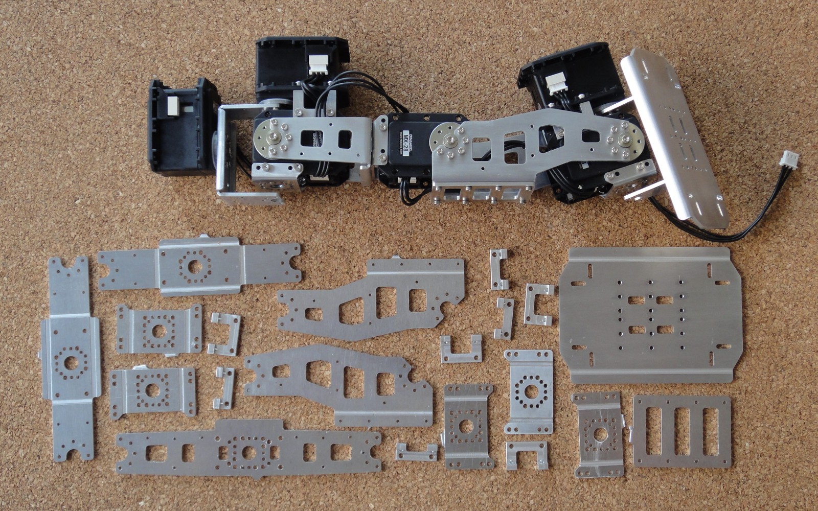
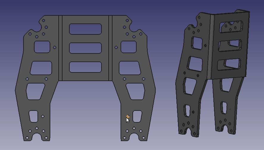
Second Leg Frames
I changed the ‘knee’ frame, my first version had a bending at the bottom, but I removed it from the design to allow my DARwIn-OP clone to have the same joint rotation range than the original design. Also, my first batch of FR07-S101 had 4 holes missing (luckily they are not used in the DARwIn-OP robot).
I still have to file and bend the frames, I’ll try to make some aluminum blocks to help on the bending. The Fabrication Manual show some examples in the appendix.
Meanwhile I am getting some 1″ and 3/8″ 6061 aluminum bars to make the FR07-F101, HN07-i101, and RX28-CAP parts in the lathe. I also have to calibrate my lathe’s quick-change cutters which is time consuming. Once done, cutting complex designs gets much easier, I’ll do a post in this later.
I cut the rest of the frames for the first leg of my DARwIn-OP clone.
No mayor issues, just the FR07-H132 2D model file had the hole pattern flipped over as I suspected (see the test cut post).
I still have missing the parts to be cut with the lathe (and I haven’t receive the ball bearings yet). Anyway I wanted to see the leg moving so I programmed a small test.
I used an ODROID-X2 board from HardKernel. It is an ARM with this specs:
– Quad core Cortex-A9 at 1.7GHz.
– 2GB RAM.
– USB 2.0 and 100Mbps Ethernet.
– Runs Android or Ubuntu.
– Can use an SD or a eMMC module (8 to 64GB) as hard drive.
– 94x90mm board.
Now that I checked that the Dynamixel MX-28T servos work OK and that it is easy to develop with the SDK, I am continuing with the rest of the first leg of my DARwIn-OP clone robot.
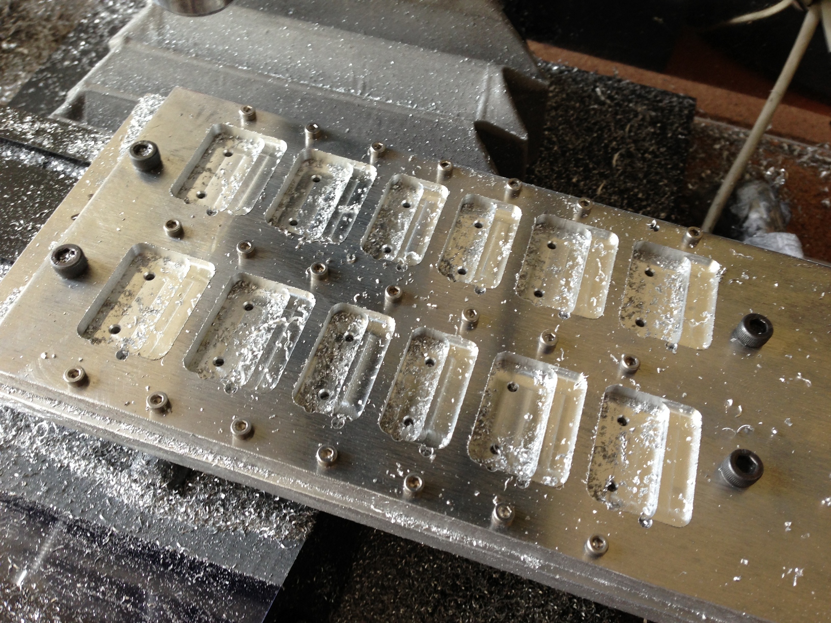
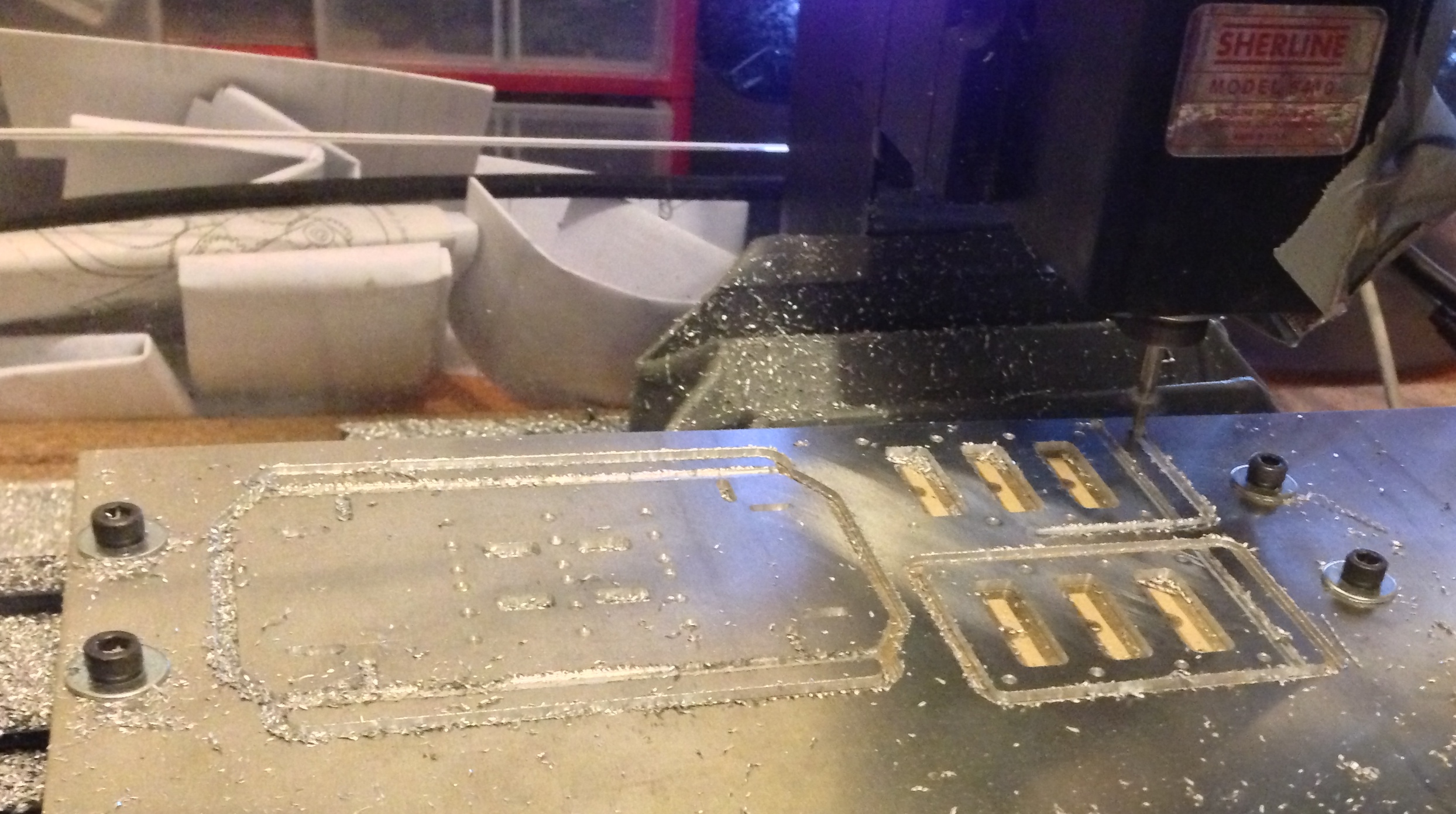
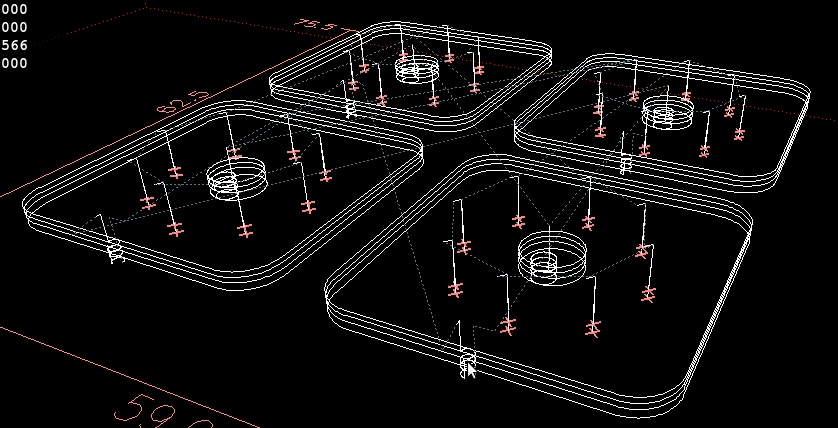
The FR07_X101 and FR07_X102 are actuator connectors for the legs and shoulders, they assemble together 2 servos to make a joint with two degrees of freedom. The DARwIn-OP requires 4 FR07_X101 and 8 FR07_X102. Acording to the design files and PDF specification from Robotis, they are 4.8mm high. I used a 1/4″ sheet as recommended in the Fabrication Manual, but a 5mm sheet should be better (less material to mill).
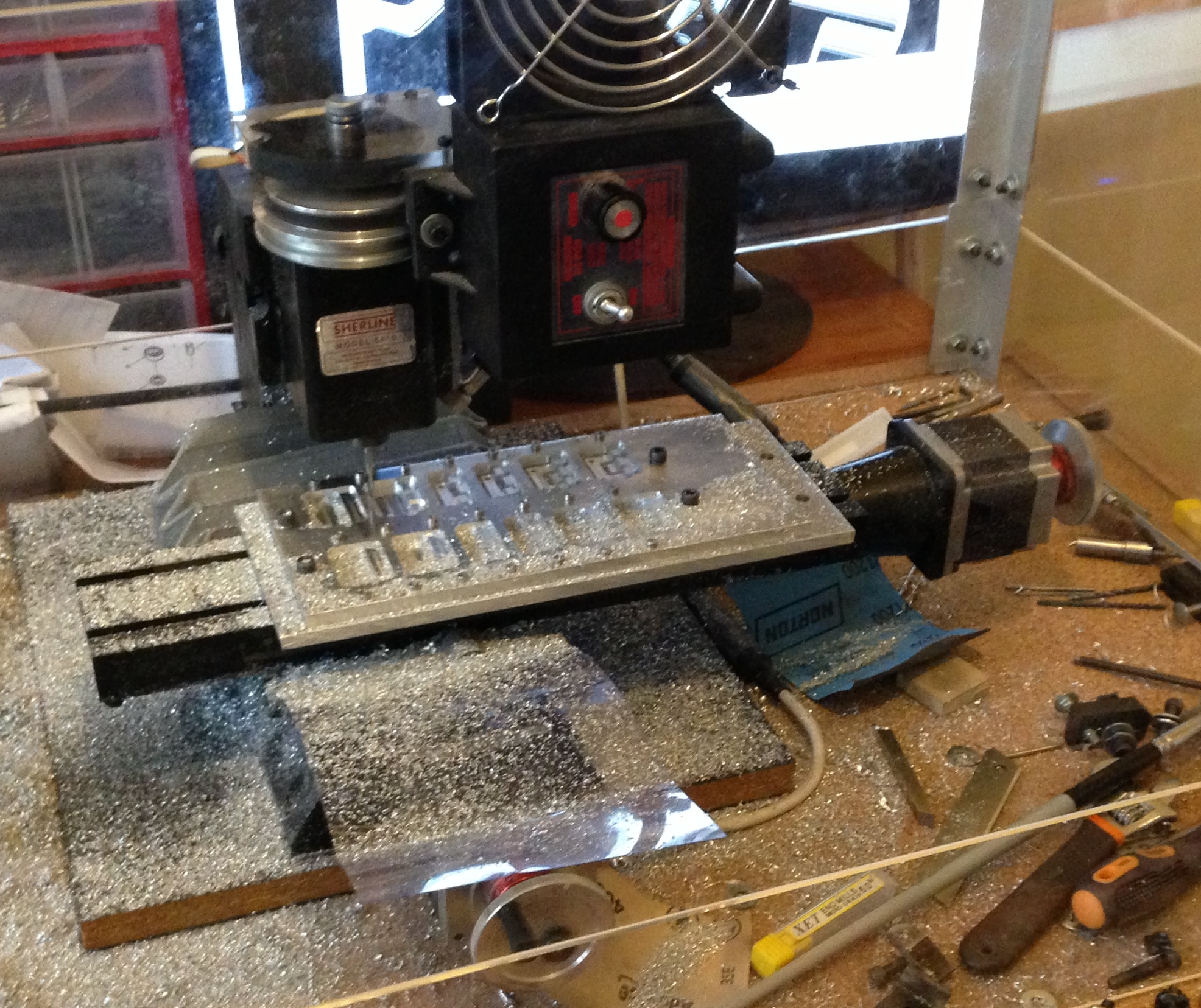
4 FR07_X101 and 8 FR07_X102 Cut
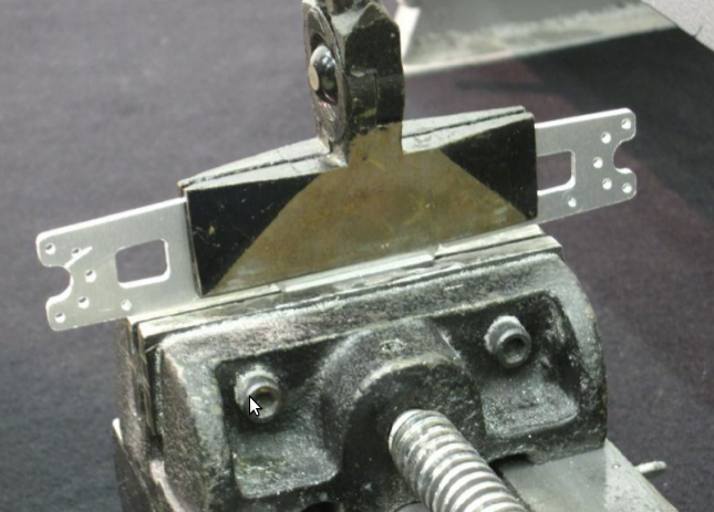
In this cut I started using an aluminum plate as base. I also started using rows of 2.5mm screws to better hold the work. This is not really needed to hold a 1/4″ sheet, but the 1.5mm and 2mm bend easily and small clearances between parts or to the sides may distort the cuts.
While I am working on milling the leg’s frames for my DARwIn-OP clone (I’ll come later on this), I decided to test the Dynamixel SDK for Linux on a PC with Ubuntu 12.04. Since I am interested in using the smaller USB2AX adapter to control the servos, I did a simple install:
I unzipped the SDK Zip file to a new folder.
As instructed in the USB2AX FAQ page, I replaced the DXL_SDK_LINUX_v1_01/src/dxl_hal.c file from the SDK with this version that correctly communicates with the USB2AX adapter.
I ran make in the DXL_SDK_LINUX_v1_01/src folder to compile the libraries.
I ran make in DXL_SDK_LINUX_v1_01/example/ReadWrite to compile a simple test example.
I connected a Dynamixel MX-28T servo with ID 1 and Baud Rate 1 mbps to the PC via the USB2AX (the USB2AX adapter only communicates at 1 mbps, and the ReadWrite example expects a servo with ID 1 with 1 mbps).
I powered up the servo.
I added my linux user to the dailout group to have RW access to the USB2AX device (/dev/ttyACM*).
I ran the ReadWrite example and it worked!
The C source code of the ReadWrite example is quite tiny and shows the basics of the API which is simple to use.
So far, I haven’t powered up any servos. They can be connected in a daisy chain 3-wire TTL bus (ground, power, and TTL communication). Each Dynamixel MX-28T has an internal PID controller and has several configurable parameters and feedback data.
I’ll do the configuration of a few Dynamixel MX-28T servos, each should be setup with its ID and baud rate at 1Mbps to be used in the DARwIn-OP clone. The ID for each servo should be from 1 to 20 depending on its location in the robot, as listed in the DARwIn-OP_Actuator ID doc or the DARwIn OP Assembly Manual doc. They come factory programmed with ID = 1 and 57142 bps baud rate and it won’t work to daisy chain 2 servos with the same ID.
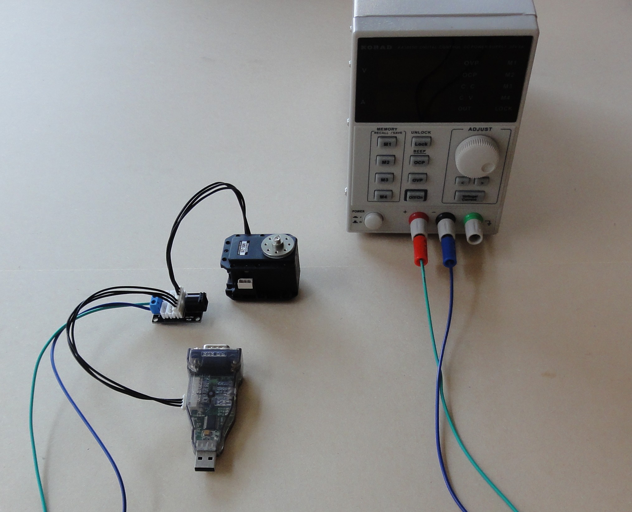
I got a Power Hub for the Dynamixel TTL bus and wires. The wiring is simple: power supply (12V) to the hub, one connection to a servo, and one connection to the USB2Dynamixel USB adapter (switched to TTL mode on the side).
Now that the first proof of concept was done with the first test cut, I am continuing with the DARwIn-OP frame parts bottom up starting with one leg.
Since my Sherline mill can manage a surface about 200x100mm. I sliced out my aluminum sheets in smaller pieces, after the first few cuts I ended up reducing the size to 150x100mm and 200x100mm pieces depending on the size of the parts to cut.
The foot is the FR07_E160 frame. The Fabrication Manual lists this part as 1.5mm thick on page 8. But the 2D and 3D model files are consistent with a 2mm thick part. I believe the manual is the one mistaken.
Foot and Knees
The first foot was cut over a 9mm wood plate. I later changed to using an 1/4″ aluminum plate as this is much more sturdy, I’ll go on this latter. The tools used are:
Centerdrill #1
drill 2mm (since at the moment I didn’t have a 2.05mm drill yet, the holes must all be 2.5mm tapped).
endmill 2.5mm for the slots (the thinner ones mesure 2.6mm wide on the model).
endmill 3mm for the cut-off. I latter stopped using the 3mm endmill as this requires an extra tool change (My mill does not a fancy automatic tool change).
With the foot I also cut a couple of ‘knees’. The DARwIn-OP may seem to be a small robot in pictures, considering it is about 45cm high (1.5 feet). But some frame parts are not as small as I imagined initially. The lower leg part FR07_H133 is about 118x106mm before bending. Considering also the endmill width, the mill is short in about 10 millimeters in its shorter Y axis.
Many frame parts of the DARwIn-OP have a kind of repeating pattern where the servo horn hooks up. To get this pattern right will help on the G-code of several frames.
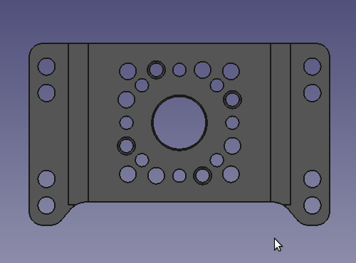
FR07-S101
The frame requires an 8mm hole and eight 2mm holes around evenly spaced in a 16 mm diameter circle. Note also, that in the pattern there are 4 holes (2.05mm) a bit rotated that will be tapped for 2.5mm screws while there are also 4 holes (2.5mm) a bit rotated the other way around, this is used to screw 2 frames together. Looking at the FR07-H132 frame’s 2D model, it has this pattern flipped over. I think it is a mistake in the 2D file.
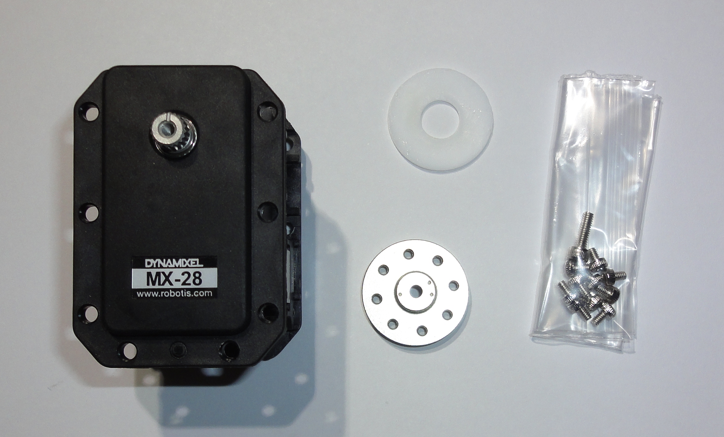
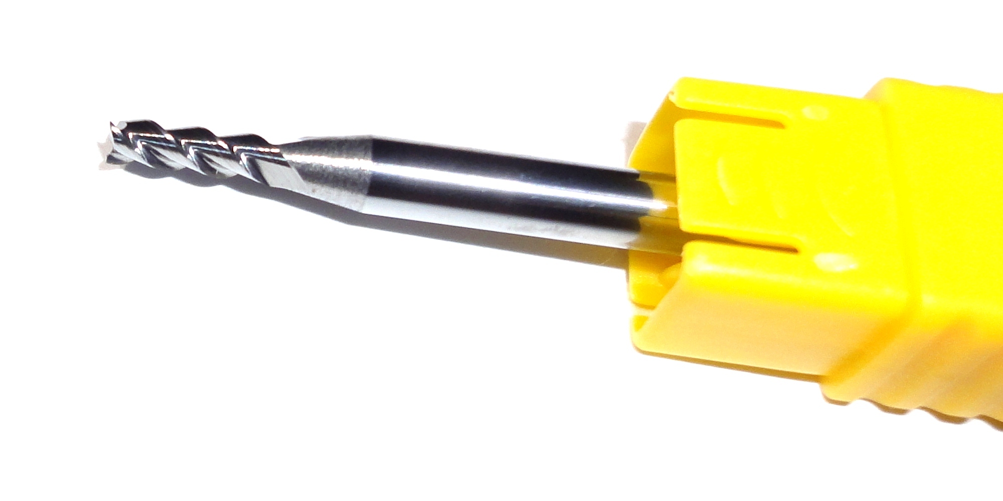
I got the aluminum sheets, the carbide 3 flute aluminum endmills, a couple of Dynamixel MX-28T servos with horns, and tap sets for 2mm and 2.5mm. I also bought a couple of FR07-I101 Bearing idler sets as samples.
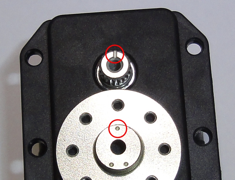
Dynamixel MX-28T with Horn
The horn has eight taped holes for 2mm screws (included) in a circle that match the repeating design pattern. The horn does not come installed, which is done with a 2.5mm hex screw (included) and this has to be done carefully since the horn has to be aligned with the shaft on the servo. Both have marks to do this. Once the horn is most of the way plugged in, it gets quite tight and it can get really difficult to get it back out.
Horn Alignment
So the first thing should be to make some trials on how much the 8mm hole should be 8mm so the horn can fit tight (so I don’t end up with frames that don’t fit the servos or are way too loose). For this I designed a few 24x24mm test square pieces with the eight 2mm holes and a the center hole varying from 8mm up in 0.1mm increments. the center hole is done with the 3mm endmill in a circular motion, so minimizing the mill’s backlash is important.
So I have to mill a bunch of aluminum frame parts and a few more have to be made on a lathe.
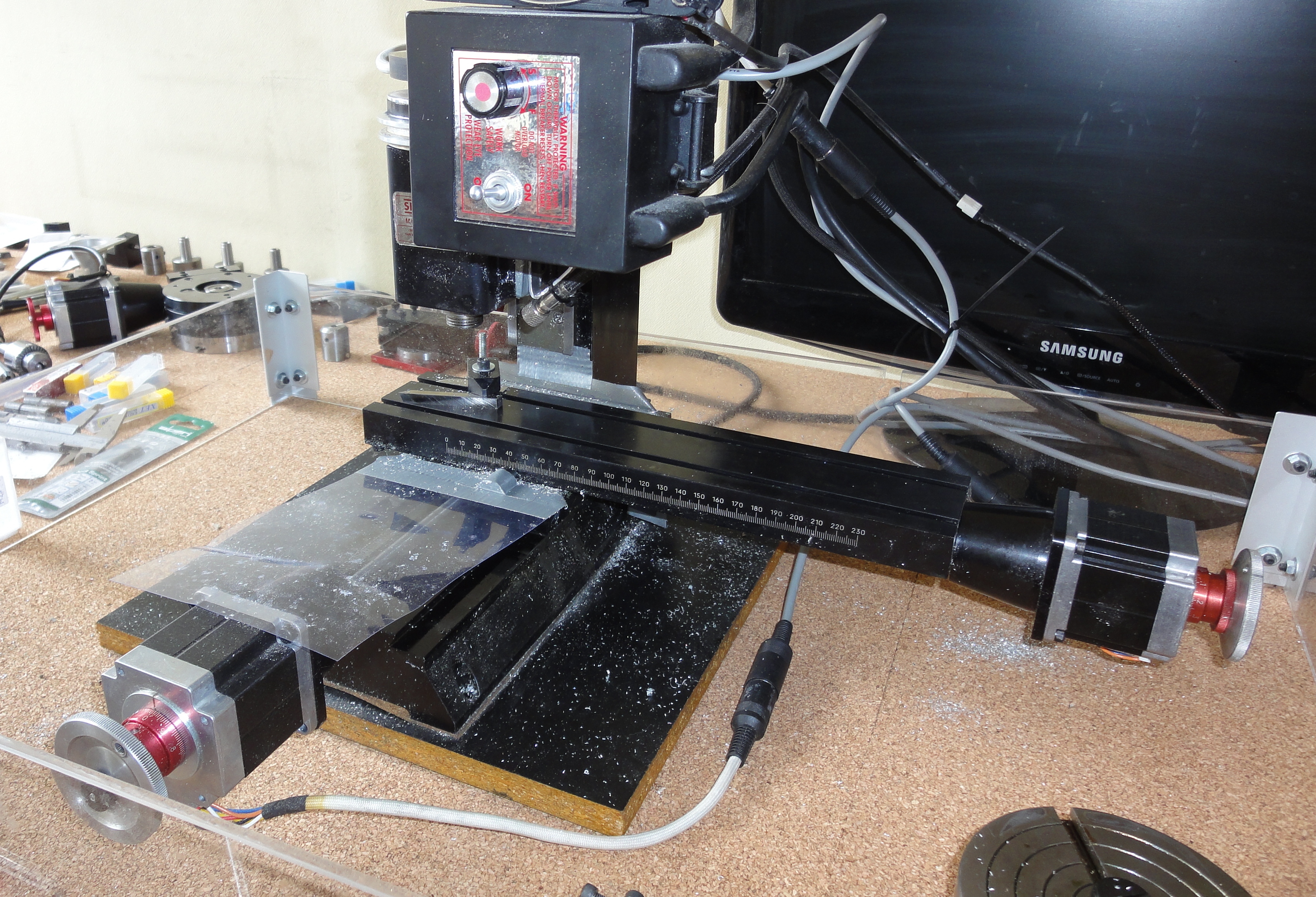
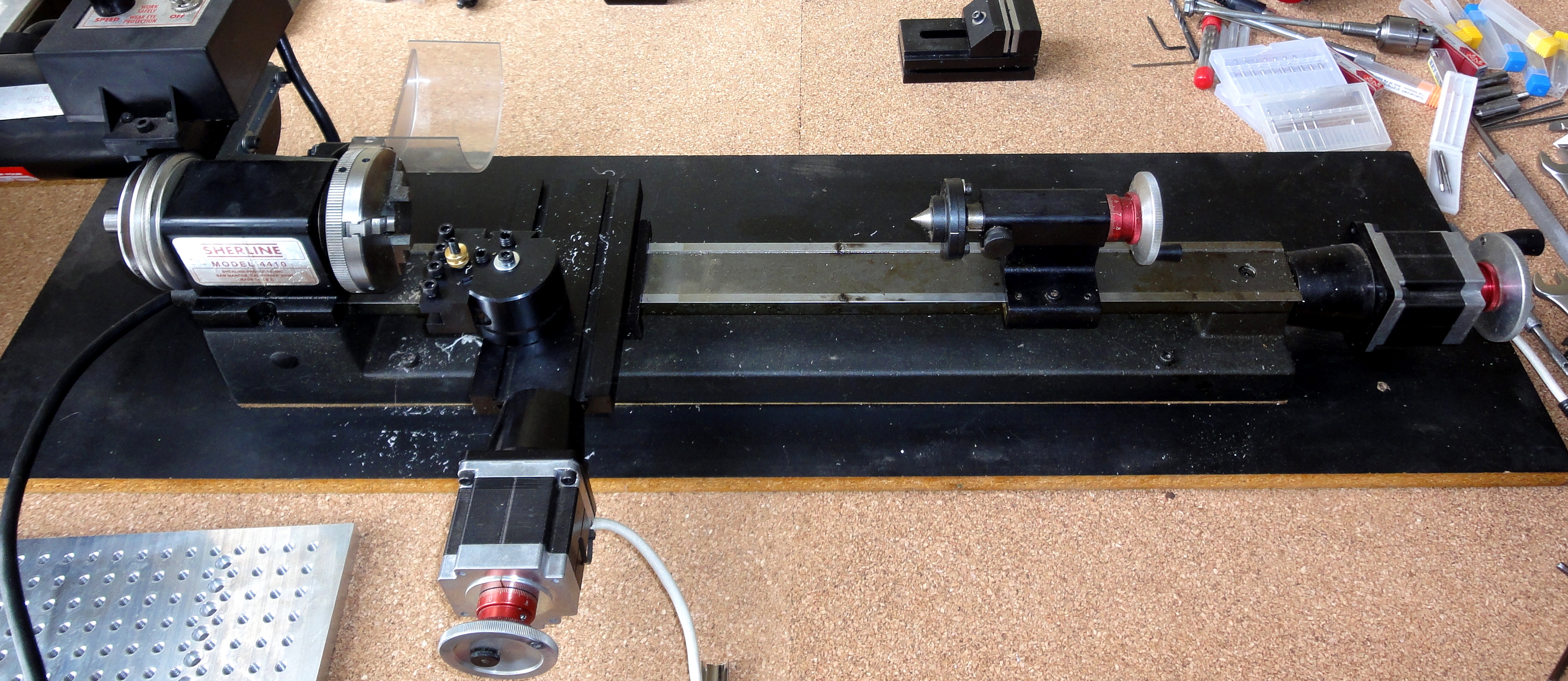
By chance, it happens that I own a Sherline mill and a lathe which I bought many years ago just to do some ‘cool’ stuff. Last year I finished installing CNC control on both and now I run them with LinuxCNC which is an Ubuntu distribution preinstalled and configured for CNC usage. LinuxCNC runs G-code programs which basically describe the path that the cutter will follow.
The Sherline mill and lathe are designed to work with soft or hard materials like stainless steel an titanium. Aluminum is no problem, though I may upgrade the pulley to the 10,000 RPM model since aluminum requires higher surface cutting speed than what you can get with the stock 2,800 RPM pulley when you are using small endmills (2.5 mm and 3 mm).
A nice thing is that the DARwIn-OP design is metric, as does my tools, so it is harder to screw up.
These tools are desktop size (I actually have them in a desktop). The mill has a working area about 200×100 mm which is too small for some of the frame parts to clone a DARwIn-OP such as the hand or the lower leg. So these parts I’ll have to redesign in several pieces that can be screwed together. A much bigger mill or a CNC-router would have been ideal for cutting a lot of pieces at once, but the tools I have can do the job.
For the mill, the cutters I’ll use are:
2.5mm and 3mm endmills. I’ll get some 2 flutes and 3 flutes carbide endmills for aluminum and check them out.
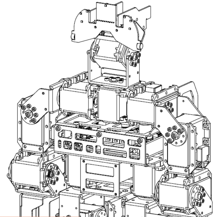
The DARwIn-OP has several mechanical documents published in this sourceforge directory. The documents are well done and fairly complete. They were written by RoMeLa at Virginia Tech.
It describes how to manufacture the frames needed to clone a DARwIn-OP. Literally the robot is a lot of servos stitched together by aluminum parts (the frames).
DARwIn-OP Frame
It recommends aluminum 5025 to make the parts. Where I live (Chile) this is not easy to find so I bought some sheets on Ebay from a US seller. Now I know this aluminum is used for naval ships so I still may have a chance here. I do not recommend using pure aluminum 1100 (which is common for sheets at least here) as it sticks on drills and endmills too much.
It lists which design files go for each part.
It lists the tools to be used and explains the manufacturing process which requires a CNC mill. The frame parts are made mostly with 2mm and 1.5mm aluminum sheets. Several bending techniques are explained to shape them 3D (depending on the tools you have). Some other parts require 5mm (or 1/4″) sheets. Also 2mm and 2.5mm tapping is required.
Frame Bending
It also estimates (US prices) the cost in tools and materials.
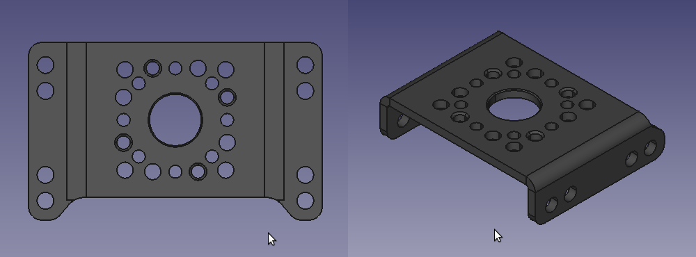
This ZIP contains 2D and 3D designs for the frame parts, all available in 3 different formats (STEP, PRT, IGS). The ‘2D’ files are actually 3D models of the unbend parts. The ‘3D’ files are 3D models of the finished parts after bending. I use FreeCAD on Ubuntu (available by apt-get) to visualize and measure the parts in STEP format.