After doing some more research, I decided to jump into configuring my DARwIn-OP’s Dynamixel Teensy 3.2 Driver Prototype to get rid of the retransmitting loop code:
void loop()
{
  if (Serial1.available())
  {
    uint8_t c = Serial1.read();
    Serial1.write(c);
  }
}
This loop just wait for a byte received by the UART and retransmit it with the same UART, which is configured with a hardware direction pin (RTS driven by the transmitter).
If I could use Teensy’s DMA (Direct Memory Access) controller to do the UART retransmission, I could empty the loop so the Teensy can be used in any other tasks without affecting the retransmission performance.
The DMA requirement is very simple:
To trigger a DMA request when a byte is received by the UART.
The DMA transfer has to be 1 byte.
The DMA transfer has to read from the UART DATA register (received data).
The DMA transfer has to write into the UART DATA register (for retransmission).
Do not involve the CPU in the process, no interrupt events.
Looking at the DMA capabilities of the Teensy’s ARM MK20DX256VLH7 CPU, it looked feasible, and after a few tries I got it working.
Now the retransmission has a smaller latency and a much smoother timing:
Teensy with UART managed by DMA
The signals in the chart are:
RX into the Teensy (from Odroid’s TX).
TX from the Teensy.
Hardward Direction Pin.
The coding has a larger setup to configure the DMA and the UART (Teensy’s interrupt driven serial API is no longer useful), but the loop() function is now empty:
#define UART_TXRTSE (2)
#define UART_TXRTSPOL (4)

#define BAUD_RATE (1000000)

void setup()
{
  int divisor = BAUD2DIV(BAUD_RATE);

  // DMA:

  // p 415 source address = uart data register
  DMA_TCD1_SADDR = &UART0_D;

  // p 415 source address offset
  DMA_TCD1_SOFF = 0;

  // p 416 transfer attributes: 8 bits
  DMA_TCD1_ATTR = 0;

  // p 417 minor byte count = 1 byte
  DMA_TCD1_NBYTES_MLNO = 1;

  // p 420 last source address adjustment = 0
  DMA_TCD1_SLAST = 0;

  // p 420 destination address = uart data register
  DMA_TCD1_DADDR = &UART0_D;

  // p 421 destination address offset
  DMA_TCD1_DOFF = 0;

  // p 423 channel link disabled
  DMA_TCD1_CITER_ELINKNO = 1;

  // p 423 last destination address adjustment = 0
  DMA_TCD1_DLASTSGA = 0;

  // p 427 channel link disabled
  DMA_TCD1_BITER_ELINKNO = 1;

  // p 424 control and status = 8 cycle stall, active
  DMA_TCD1_CSR = DMA_TCD_CSR_BWC(3) | DMA_TCD_CSR_ACTIVE;

  // p 402 enable DMA REQ channel 1.
  DMA_SERQ = DMA_SERQ_SERQ(1);

  // clock setup
  // p 252-259 system clock gating
  SIM_SCGC6 |= SIM_SCGC6_DMAMUX;
  SIM_SCGC7 |= SIM_SCGC7_DMA;
  SIM_SCGC4 |= SIM_SCGC4_UART0;

  // wait for clocks to become stable.
  delay(500);

  // p366 dma mux channel configuration
  DMAMUX0_CHCFG1 = DMAMUX_ENABLE | DMAMUX_SOURCE_UART0_RX;

  // UART:

  // p 1222 UART0 Control Register 5 request DMA on receiver full
  UART0_C5 = UART_C5_RDMAS;

  // RX TX pins
  CORE_PIN0_CONFIG = PORT_PCR_PE | PORT_PCR_PS |
                     PORT_PCR_PFE | PORT_PCR_MUX(3);

  CORE_PIN1_CONFIG = PORT_PCR_DSE | PORT_PCR_SRE |
                     PORT_PCR_MUX(3);

  // p 1208 uart0 baud rate
  UART0_BDH = (divisor >> 13) & 0x1F;
  UART0_BDL = (divisor >> 5) & 0xFF;
  UART0_C4 = divisor & 0x1F;

  UART0_C1 = UART_C1_ILT;
  UART0_TWFIFO = 2; // tx watermark
  UART0_RWFIFO = 1; // rx watermark
  UART0_PFIFO = UART_PFIFO_TXFE | UART_PFIFO_RXFE;

  UART0_C2 = UART_C2_TE | UART_C2_RE | UART_C2_RIE;

  // enable PIN 6 as hardware transmitter RTS with active HIGH.
  CORE_PIN6_CONFIG = PORT_PCR_MUX(3);
  UART0_MODEM = UART_TXRTSE | UART_TXRTSPOL;
}

void loop()
{
}
Actually, now I am running the typical ‘blink’ in the loop() function just so I know the Teensy is running.
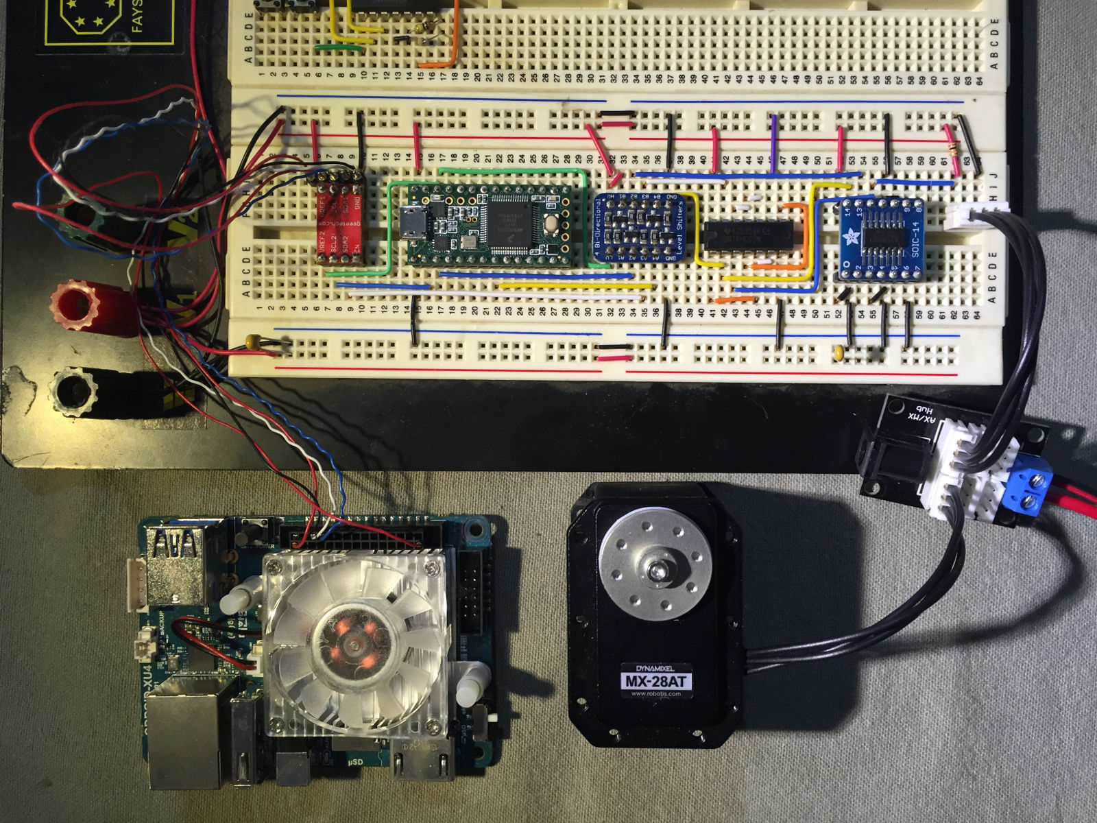
I replaced my initial TTL prototype with a Teensy 3.2, this is a development board with a 32 bit 72MHz ARM CPU in a small 35×18 mm board.
Odroid-XU4, Teensy 3.2 and Servo MX-28 Setup
I selected this board because it has several serial interfaces (UART) supporting:
1 an 3 Mbps, baudrates that can be used with the MX-28 servo.
A hardware direction pin. Its hardware RTS pins can signal when the UART is transmitting, (by configuring the RTS being driven by the transmitter instead of the receiver part of the UART, sadly the Odroid-XU4 (as several other boards) does not support this option from what I gather from its available CPU documentation.
Also Teensy’s site documentation seems good enough.
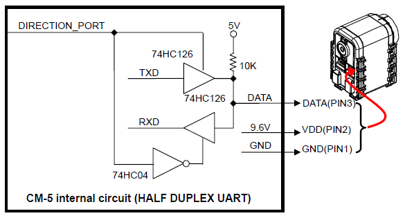
Robotis documents this setup to interface a UART to the Dynamixel bus. It requires a UART and a direction pin with 5V logic:
Robotis Citcuit Interface to Dynamixel Bus
So by placing a Teensy 3.2 between the Odroid-XU4 and the Dynamixel bus I can generate the direction pin by hardware instead of a delay-prone software implementation.
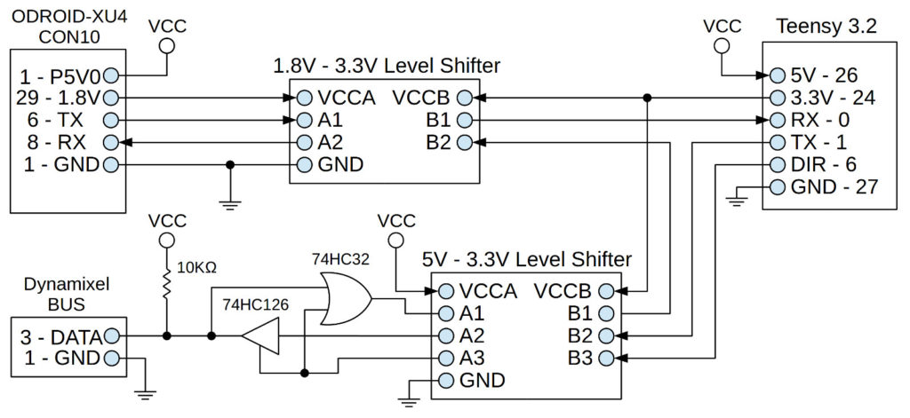
This is a simplified schematic of the setup, I changed the receive buffer with an OR gate in order to avoid a pull-up resistor:
Odroid-XU4, Teensy 3.2, Dynamixel Schematic
This setup only uses 1 UART on the Teensy. Teensy’s function is only to retransmit to the Dynamixel Bus and to generate the direction pin. Meanwhile the feedback from the Bus goes directly back to the Odroid, there is no need to pass it through the Teensy. This way, this setup can be used with other micro-controllers that only have 1 UART and there is no extra delay in the feedback. The Odroid provides 1.8V and 5V that power the Teensy and level shifters, and the Teensy provides 3.3V that also powers the level shifters.
Probably my final setup will use 2 UARTs in the Teensy, so it can generate a feedback to the Odroid and participate as another device in the Dynamixel bus (under its protocol) and have an extra function, like PWM or analog I/O. It will depend if there is enough idle time in the bus to add more commands, but the current 8ms control cycle in the DARwIn-OP software is very limited.
The Teensy’s site Documentation for the UART is strait forward. It is programmed with an add-on to the Arduino IDE called Teensyduino.
The following (and flawed, as pointed later) program is easily derived to retransmit through the serial interface with a direction pin:
void setup()
{
  Serial1.begin(1000000);
  Serial1.transmitterEnable(6);
}
void loop()
{
  if (Serial1.available())
  {
    uint8_t c = Serial1.read();
    Serial1.write(c);
  }
}
In this example pin 6 is setup as the direction pin to signal when a transmission is in progress.
On the Odroid-XU4 side, the standard Dynamixel library can be used. The only change it needs is the name of the serial device which is /dev/ttySAC0 for the UART exposed in the Odroid’s expansion connector 10.
This configuration at 1Mbps worked interacting with a MX-28 servo. But 2 things didn’t work as planned:
There was a delay of about 5 bytes (50 us) in the retransmission. I was expecting over 1 byte, but not that much.
The direction pin 6 did not work properly all the time (this was not noticeable right away).
Retransmission delay
Teensy Retransmission Delay
The Teensy’s ARM MK20DX256VLH7 CPU documentation describes in chapter 47 the UART interface. In section 47.3.21 it describes the UART_RWFIFO register that configures the threshold for the receive buffer before interrupting the CPU, its value is 1 after reset.
By checking the Serial1.begin() library source code I noticed that this UART_RWFIFO threshold is increased to 4. This allows for a lower CPU usage in handling receiving data, but it adds latency. Also, the library code handles the UART by hardware interrupt events. So actually the CPU knows that data was received after the first 4 bytes have being received (if less than 4 bytes is all that is transmitted, the CPU will also be notified by an idle interrupt event). The Serial1.available() function does not query the UART, it only checks some software buffers that are actually filled through interrupt handling.
Since now I am only using the Teensy to retransmit, I lowered the threshold back to 1 byte by modifying the setup function in my code:
void setup()
{
  Serial1.begin(1000000);
  Serial1.transmitterEnable(6);

  // set receiver buffer threshold for interrupt back to 1.
  uint8_t c2 = UART0_C2;
  UART0_C2 = c2 & ~UART_C2_RE; // disable C2[RE] (receiver enable)
  UART0_RWFIFO = 1;            // set receiver threshold
  UART0_C2 = c2;               // restore C2[RE]
}
void loop()
{
  if (Serial1.available())
  {
    uint8_t c = Serial1.read();
    Serial1.write(c);
  }
}
UART0_C2 and UART0_RWFIFO point to hardware configuration registers and are defined in Teensy’s library header files. The CPU’s hardware UART #0 maps to the library’s Serial1 C++ object.
Flawed Direction Pin
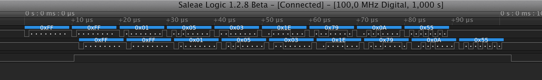
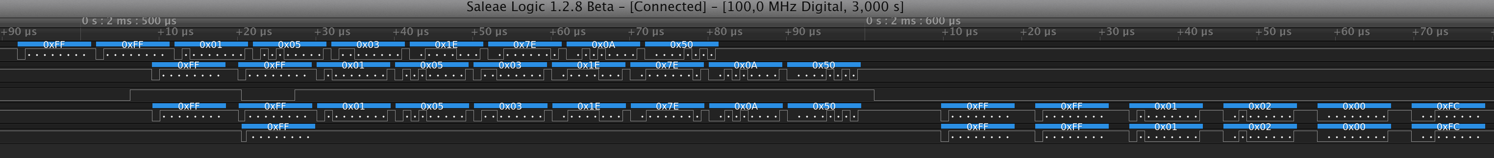
After stress testing, 1 in every 30 to 100 commands to the servo would result in a timeout waiting for the servo’s response. So after several attempts I captured some cases where the direction pin worked incorrectly.
Direction Pin Failure 1 – Servo still responds, but there is an extra initial return byte.Direction Pin Failure 2 – Servo gets byte 4 corrupted, no response.
In the digital probe chart, the signals are:
TX from Odroid-XU4
TX from Teensy 3.2 retransmission
Direction Pin from Teensy 3.2
Dynamixel Bus
RX back to Odroid-XU4
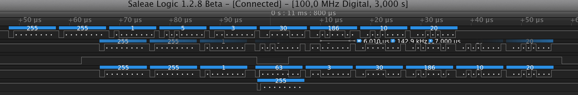
Normally, the direction pin works okay, but sometimes it would deactivate during transmission. Failure chart 1 shows a case that do not affect the message to the servo, but the Odroid receives back an extra initial 0xFF byte. Failure chart 2 shows a message being corrupted, the 4th byte in the Dynamixel bus has value 63 but should have value 5.
During my previous check at the Serial1 library source code I noticed that transmitterEnable functionality is actually implemented by software. It is not using the hardware RTS feature of the UART. From the signal analyzer probing, it is obvious that this software implementation is flawed. Since I am interested in a hardware solution, I did not try to fix the library source code, but I did notice at least one race condition not properly handled.
So after reviewing again Teensy’s ARM MK20DX256VLH7 CPU documentation, I found the hardware solution in section 47.3.14, the UART_MODEM configuration register describes how to configure RTS to signal when the UART transmitter is active.
Also this other ARM K20 document describes the hardware pins’ multiple configuration. In chapter 8.1, it lists how the different internal hardware signals can be multiplexed to the external CPU pins. In particular, CPU pins 25, 37, and 61 can be configured as RTS for UART 0. These are CPU pins, not Teensy’s board pins. This schematic shows that only 2 pins in Teensy’s board are available, pin 6 (connects to CPU pin 61) and pin 19 (connects to CPU pin 37). After digging a bit some other code around I found how to program the configuration of a pin, in particular, pin 6 as RTS (ALT3 functionality).
This is the final version for the setup to use a hardware controlled direction pin, the call to the flawed Serial1.transmitterEnable() library API was removed.
#define UART_TXRTSE (2)
#define UART_TXRTSPOL (4)

void setup()
{
  Serial1.begin(1000000);

  // set receiver buffer threshold for interrupt back to 1.
  uint8_t c2 = UART0_C2;
  UART0_C2 = c2 & ~UART_C2_RE; // disable C2[RE] (receiver enable)
  UART0_RWFIFO = 1;            // set receiver threshold
  UART0_C2 = c2;               // restore C2[RE]

  // enable PIN 6 as hardware transmitter RTS with active HIGH.
  CORE_PIN6_CONFIG = PORT_PCR_MUX(3);
  UART0_MODEM = UART_TXRTSE | UART_TXRTSPOL;
}
void loop()
{
  if (Serial1.available())
  {
    uint8_t c = Serial1.read();
    Serial1.write(c);
  }
}
The direction pin works flawlessly and has a more consistent timing:
Teensy Driver Working Fine
Now I need to shrink this prototype to a circuit board under the Teensy 3.2.
As I am using an Odroid-XU3 (and now I’ll be upgrading to an Odroid-XU4) with an USB2AX adapter to interface the Dynamixel MX-28 servos, I am getting annoyed by the USB delay of the adapter.
As the USB2AX is an USB 1.1 device and USB 1.1 has a 1ms time framing for transmitting and receiving data. Any Dynamixel commands takes at lease 2ms which is unacceptable. Even using bulk read and write instructions (which are taking longer time as I connect more servos) I would like to comply to the 8ms control loop in the original DARwIn-OP programming. So I am getting too close to the limit.
Luckily, as described in odroid forum, the Odroid’s UART interface can be setup to the Dynamixel’s bus specifications (8 bit, 1 stop, No Parity) at 1Mbps and all the way up to 3Mbps!!!
So I am working on a driver to implement the Dynamixel’s TTL half-duplex serial interface with just the RX and TX pins from the Odroid (without any control pin to command the half-duplex direction). This way it can be use with simple UARTs such as the one found on the Odroid which do not have a hardware output to signal an active transmission in progress (and I don’t want to use a software controlled gpio to avoid time mismatches).
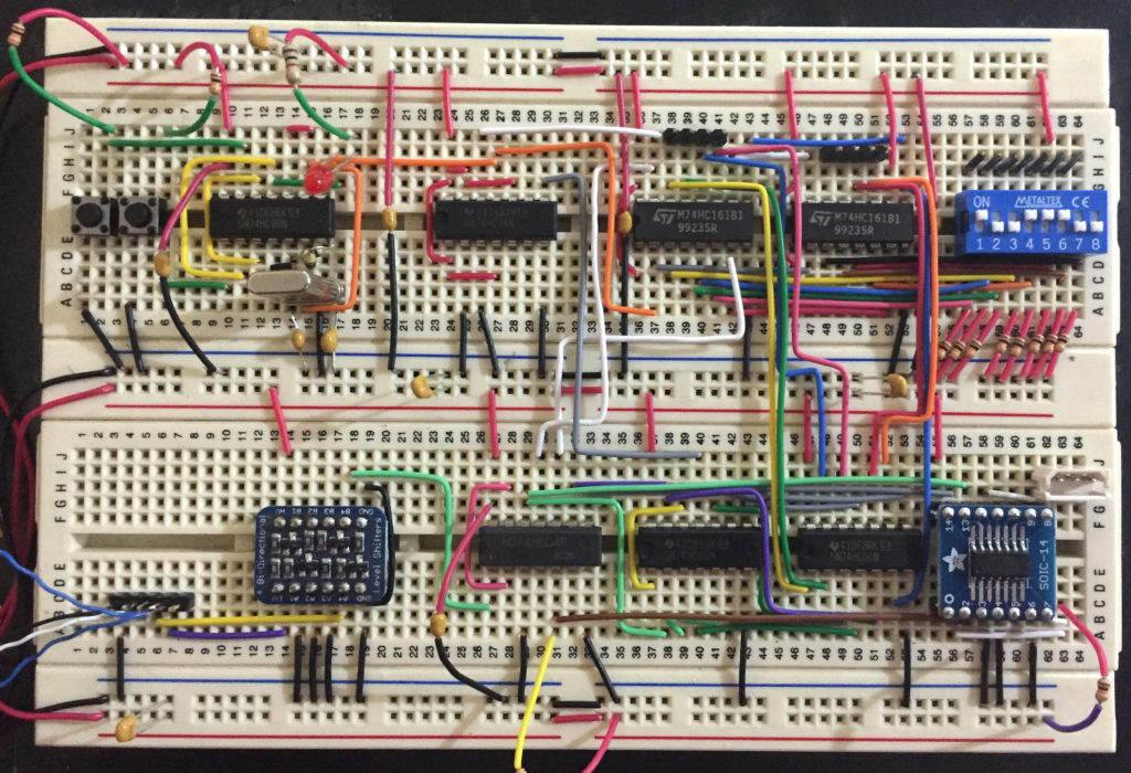
So far I did a TTL prototype (Odroid’s UART is 1.8V while Dynamixel bus is 5V), but I’ll continue by shrinking this to a micro-controller soon.
TTL servo driver prototype
Before this I was working on using an SPI UART to replace the USB2AX, but that is going to the trash now.
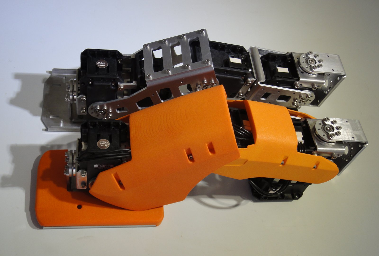
Continuing with my DARwIn-OP clone robot, I am now cutting the shoulder parts.
After most of the parts done, I am finally getting a better setup for cuts in my CNC Sherline mill.
First I started fixing the aluminum sheets over small MDF board, cutting with 3mm endmills, a center drill, and several drills (1.6mm, 2.0mm, 2.05mm, 2.5mm, and 2.6mm), later I moved to a smaller 2.5mm endmill for better score’s finish. Following the DARwIn-OP Fabrication Manual, I placed checks on the cutoff path so the parts would not come loose. Later I replaced the MDF base board with an aluminum plate. Then I tested only using a single 1.5mm endmill for everything, but I didn’t like the surface finish and the holes weren’t perfect enough.
Now I think I have a better setup:
Following a friend’s setup, I replaced my mill’s aluminum matrix plate with a MDF board with the same size and attachment.
I fix the aluminum plates to the MDF board with several 2.5mm x 10mm screws around the parts to be cut. For this, I drill the MDF with a 2mm drill, 9mm deep. After several cuts, the MDF can easily be changed with another one.
I went back to milling with a 2.5mm endmill (or 2mm endmill depending on the detail of the part, the Fabrication manual recommends a 3mm endmill, but some of the designs require 1mm radius cuts).
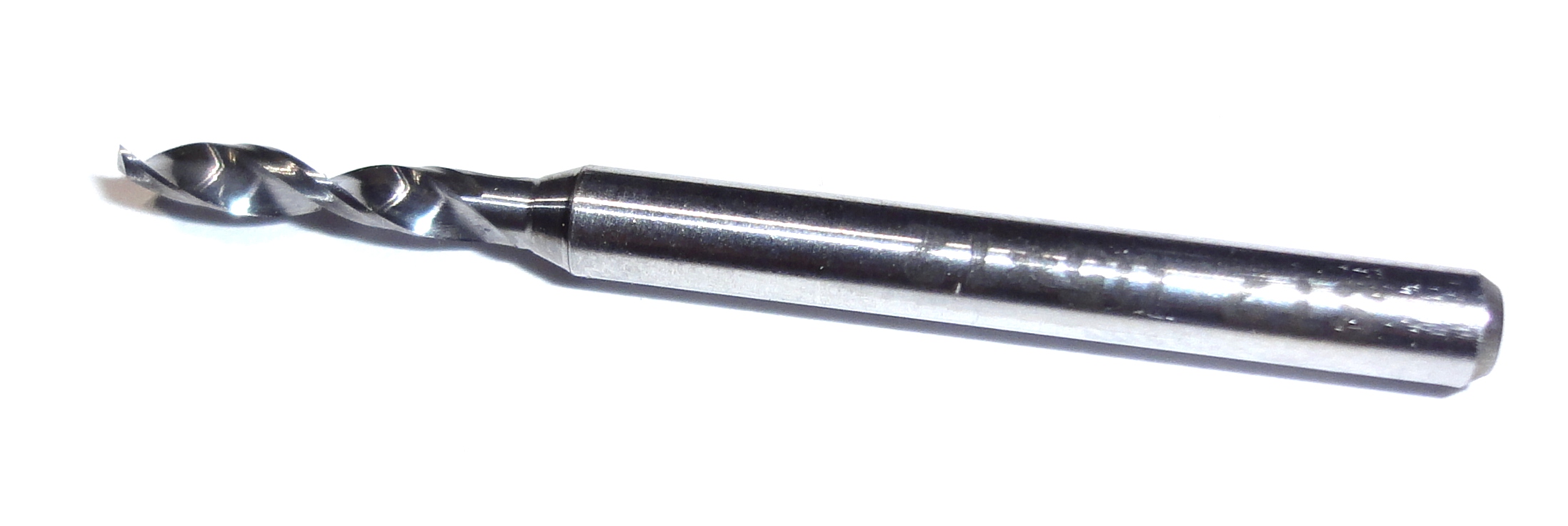
I went back to using drills of size 1.6mm, 2.0mm, 2.05mm, 2.5mm, and 2.6mm. But since these are carbide drills with a wider (1/8″) shaft, I am not using a center drill any more to mark the holes. (After a few tests, I saw no hole displacements).
Drill
I am not leaving checks on the cutoff paths anymore. Now I screw the part to the MDF before doing a complete cutoff. I use some of the original holes of the part for this.
For any big slot that need to be emptied on a part, I mill it completely so no sizable aluminum bit that gets loose could break the endmill. If the slot is too big, then I would also place some screws on it so I don’t have to mill it all off.
Also, I replaced the Sherline mill headstock with an ER-16 model (from Sherline also). This allows for much easier tool changes, and ER-16 collets are available such as Techniks collets with very good accuracy (low TIR) which is important to keep small endmills well centered.
I upgraded the mill to 10k RPM (with a 10k RPM pulley set from Sherline).
I am cutting with the 2.5mm endmill at 5k RPM, 200mm/s speed, and 0.4mm depth of cut. For the 2mm endmill, I change the depth of cut to 0.25mm.
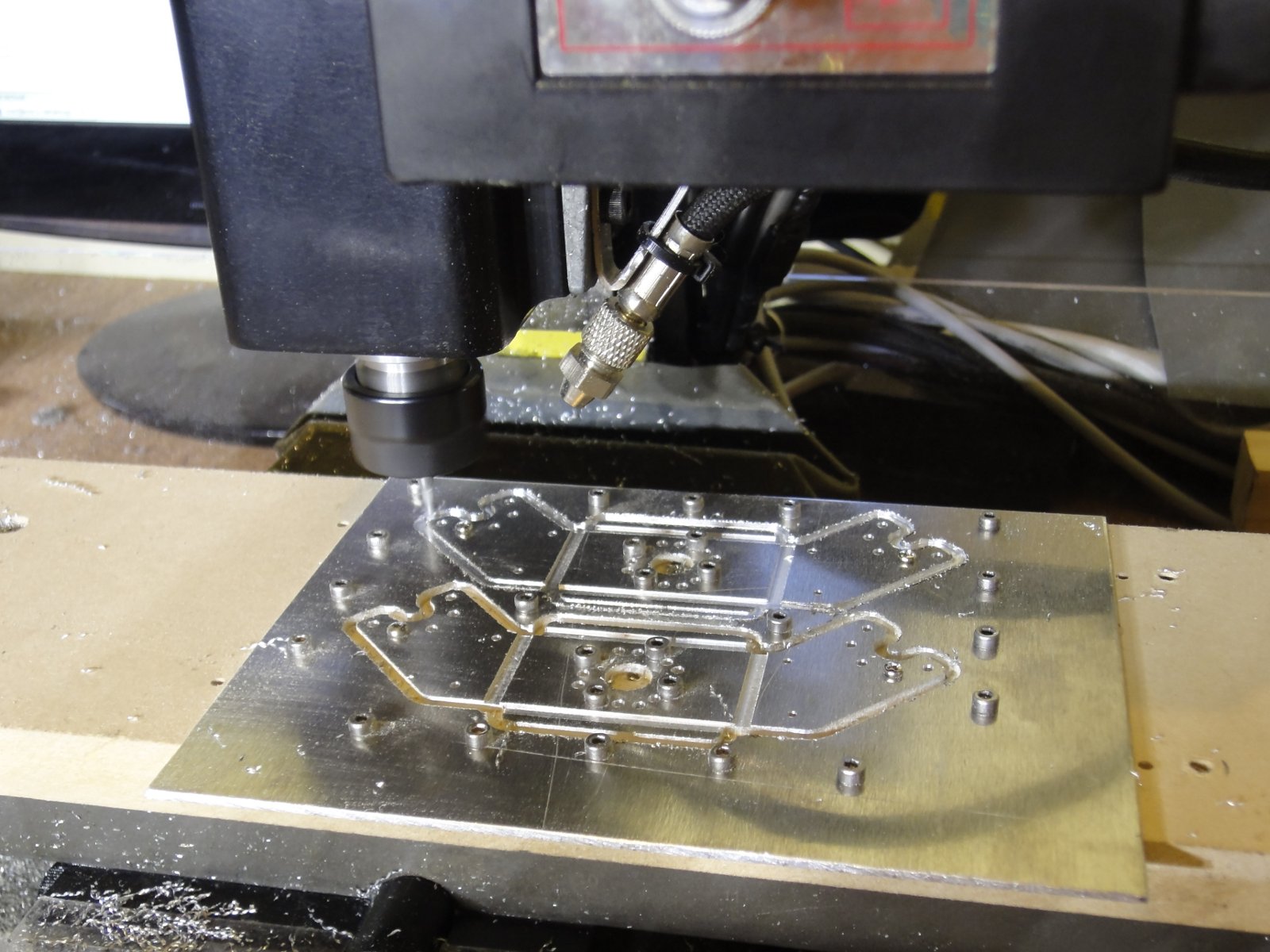
I don’t use any lubricant, only an air blower to keep the cutting area clean (see photo).
The following picture shows the setup while milling the last cutoff:
Cutting DARwIn-OP shoulders
The older gcode files I wrote don’t follow this setup, but can easily be updated.
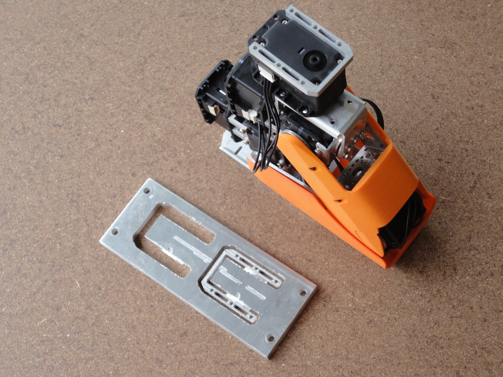
My DARwIn-OP clone is taking shape. I mounted the chest section.
DARwIn-OP up to the shoulders.
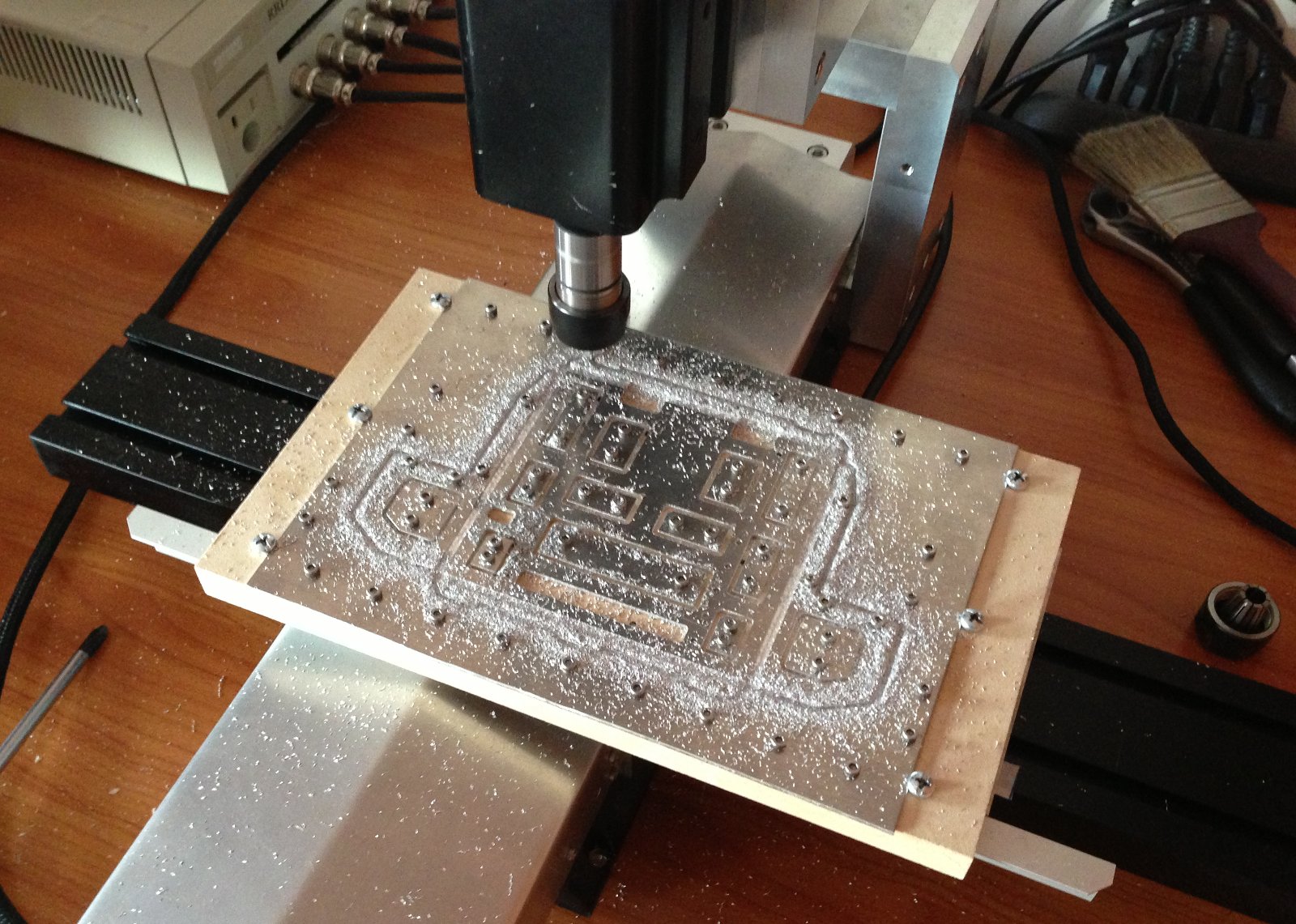
The chest parts (where the computer is mounted) are pretty big and my mill doesn’t have enough range in the Y axis to mill it in one cut. Luckily a friend that I met through this blog helped me with the cuts. He lives in my city and has a modified Sherline mill with bigger range. Also he is a Sherline dealer in Chile and works on CNC projects and has several interesting posts on his own blog at metaltronics.wordpress.com.
Milling on the modified Sherline mill.
For the chest cuts, we tested using only a 1.5mm endmill, even for holes (1.6mm the smallest). For future cuts I will use bigger endmills such as 2mm o 2.5mm as in my previous cuts, the 1.5 endmill requires a depth of cut too small (we used 0.2mm) and are more fragile.
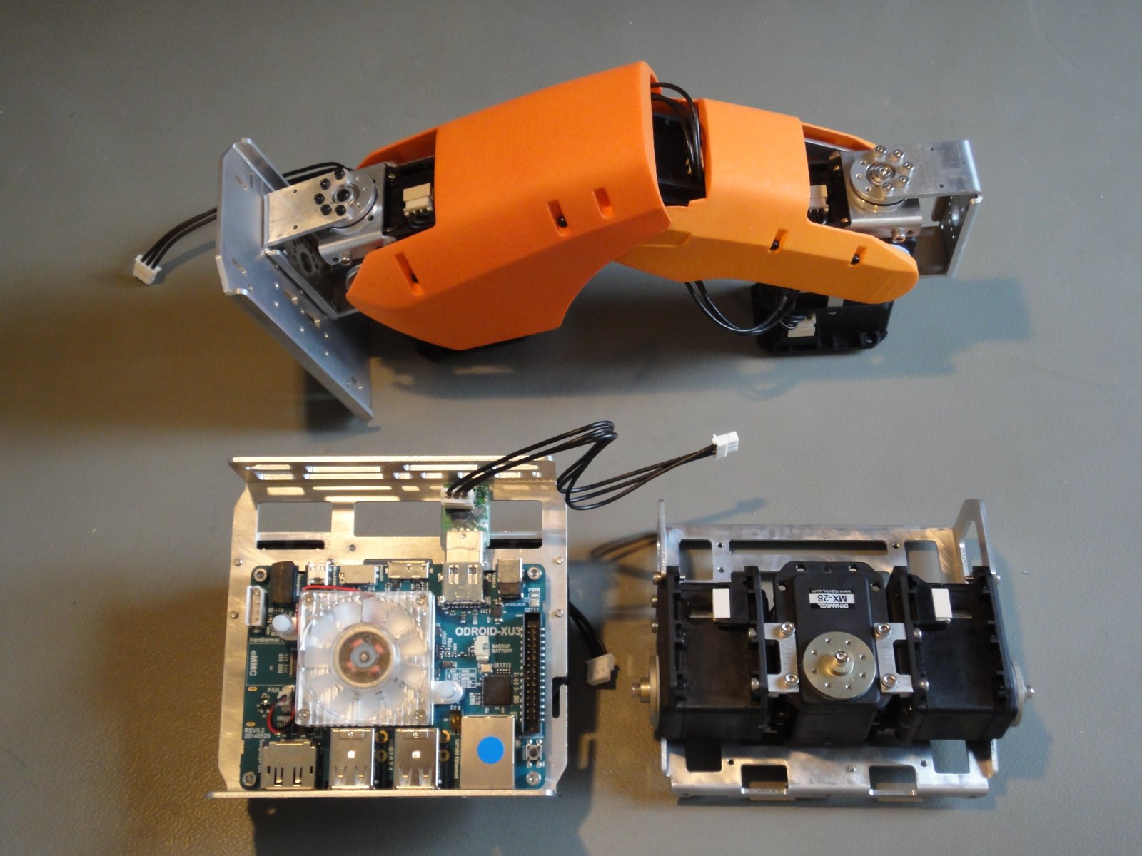
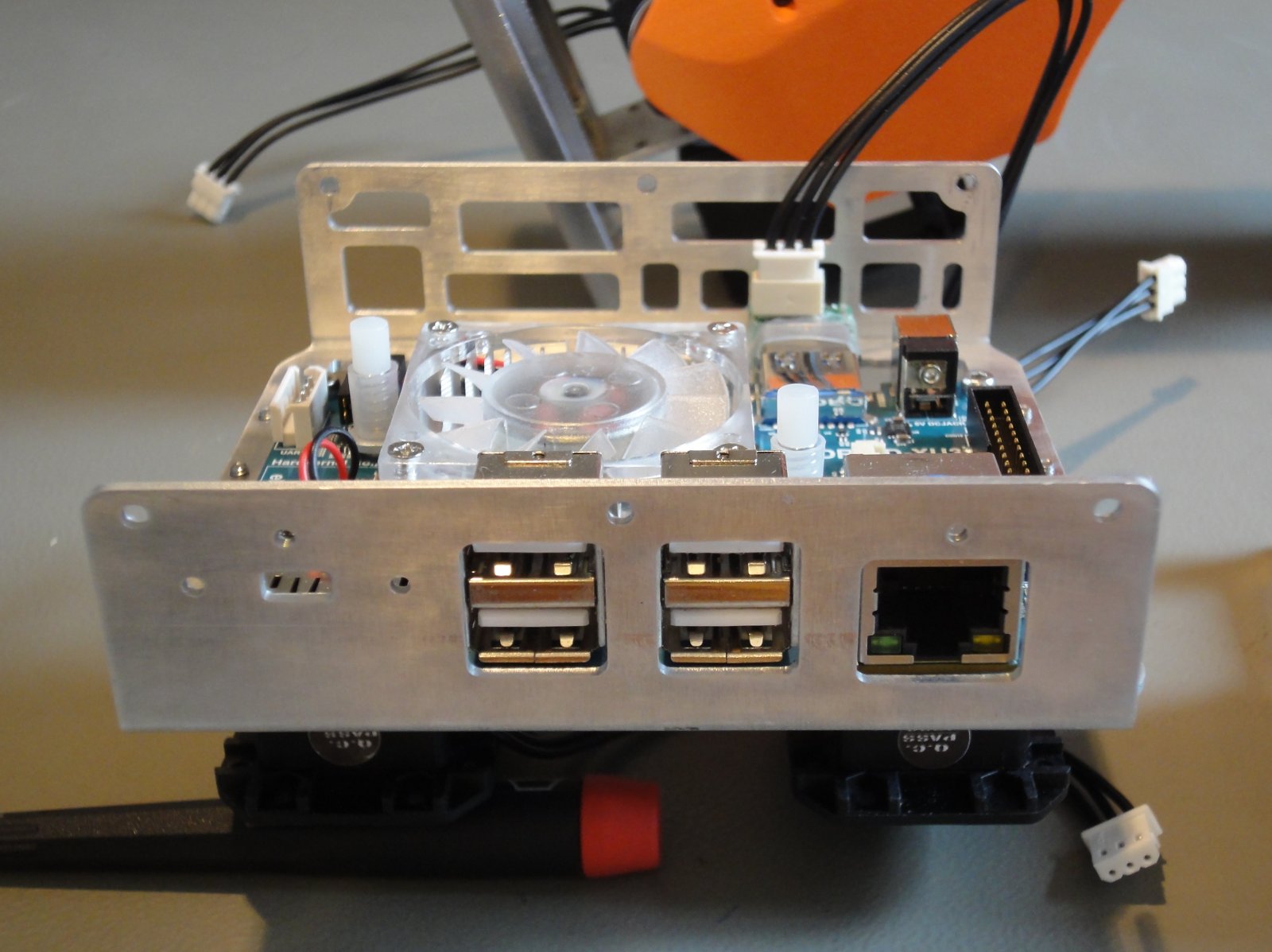
Since I am not going to use the original DARwIn-OP electronics (Fit-PC + CM-730 controller), I modified the chest parts to allow mounting an Odroid-XU3, in particular for access to the rear ports and mounting points.
Chest parts with mounted Odroid-XU3 (and USB2AX) and shoulder + neck servos.
The Odroid-XU3 fits without problem, but to mount the USB2AX (interface to servos) I had to adjust the TTL connector to a vertical position.
In the rear, I exposed the Ethernet port, 4 USB ports and a micro-HDMI (with a 15cm extender). Probably I’ll leave only 2 USB ports exposed, removing one connector to allow for more internal USB ports.
Odroid-XU3 exposed ports.
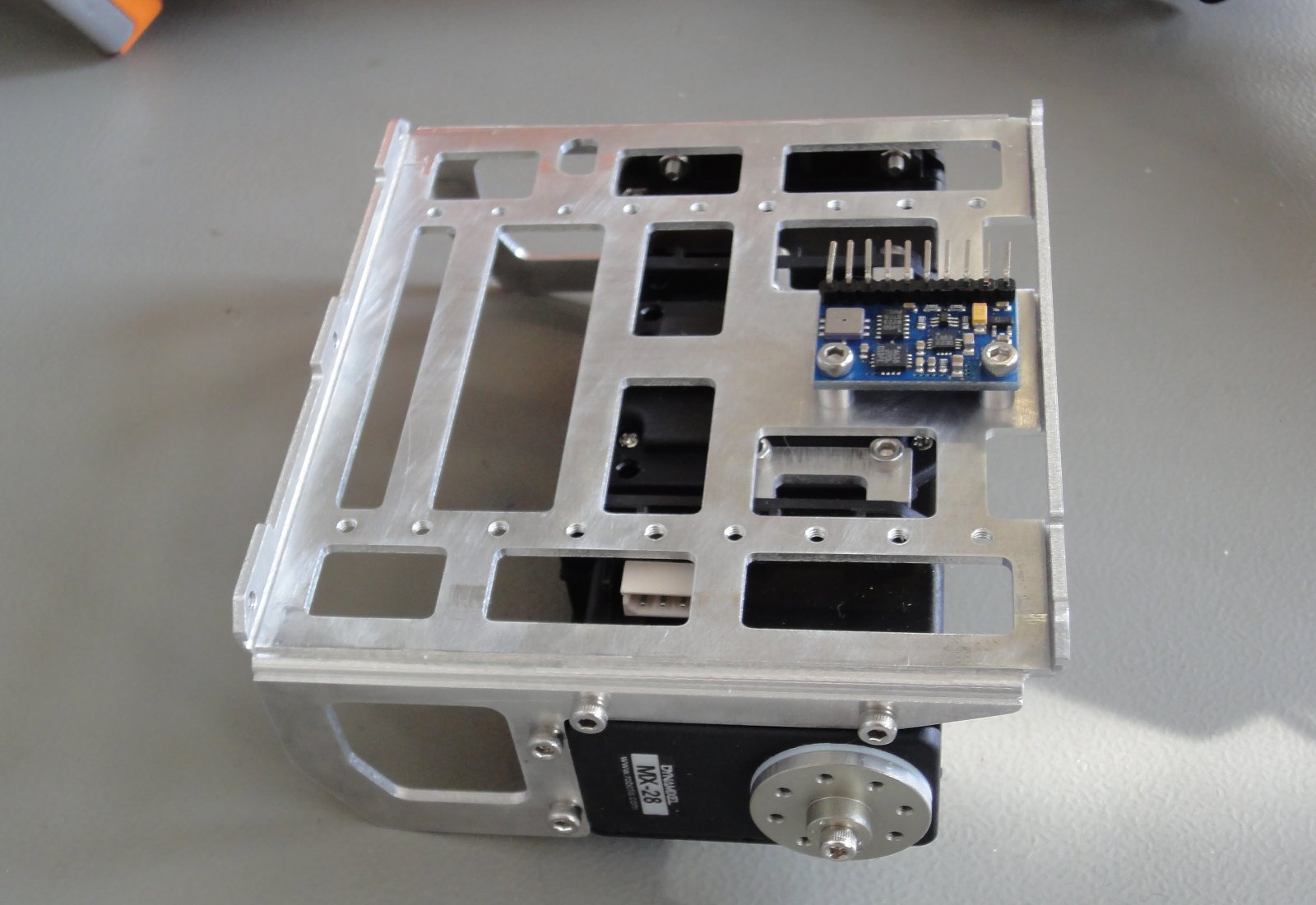
The upper chest part was modified to mount a 10-DOF, centering the accelerometer chip in the same place where the original CM-730 controller has its own. Additional holes tapped to 2.5mm were added for future components.
10-DOF mounted on upper chest part.
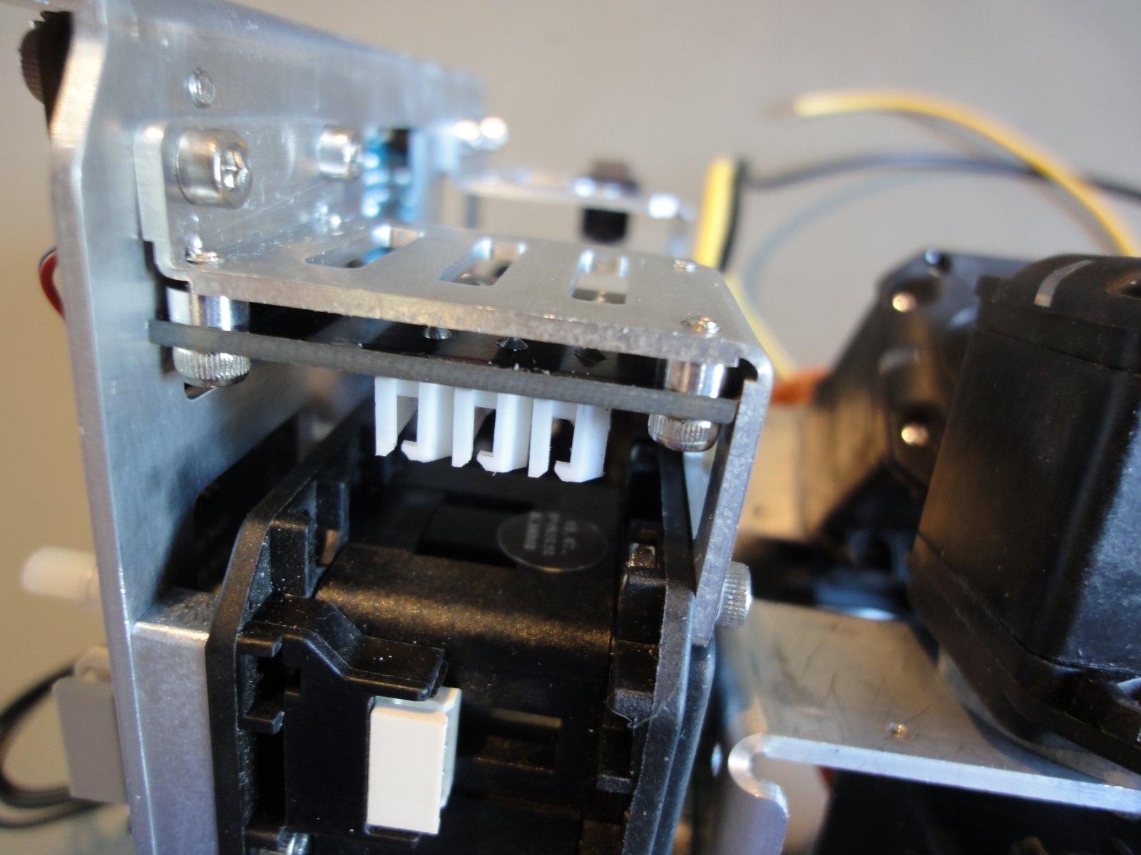
Because of the change of electronics, a 6 port TTL dynamixel hub is needed to connect the servos. In the rear there is just enough space to mounted.
I milled the PR13_B_SPACER_PELV mounting brackets which go on top of each leg.
Leg Mounting Brackets
The brackets are necessary to attach the legs to the chest section where the main computer resides. Currently I am redesigning the chest parts to fit a Odroid-XU3 computer, the main changes are in the position of external USB and Ethernet ports.
The cut files for the mounting bracket are in SourceForge here. In the README file is the list of gcodes files.
For future parts I’ll try to change the cutting strategy for milling. Instead of using several drills and endmills, I’ll try to use a single 1.5mm endmill for all cuts, avoiding tool changes.
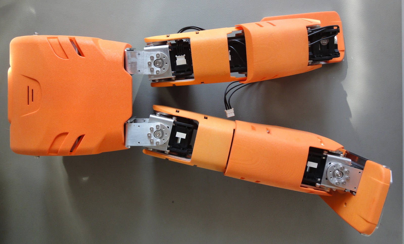
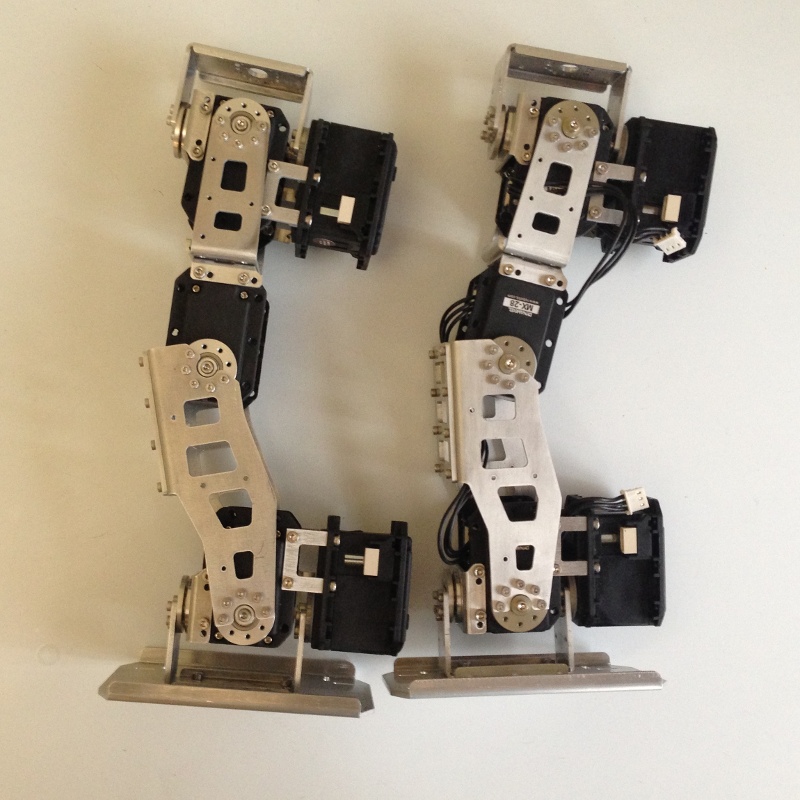
I finished assembling the second leg for my DARwIn-OP clone.
2 DARwIn-OP legs
I finished writing the gcode cut files for the pelvic mounting brackets (PR13_B_SPACER_PELV) which go between the legs and the chest, and I’ll be cutting them soon.
Meanwhile I was redesigning the chest brackets to accommodate the ODROID-XU ARM computer instead of the original FitPC with an Intel processor. As an alternative, I am also considering to use an ODROID-U3 computer, with has a smaller footprint and a less powerful ARM processor (and consuming less power). The latest ODROID-U3 (Revision 0.5) has an native SPI interface, so which could be used to interface sensors (accelerometer and gyroscope).
But now, Hardkernel is going to release the ODROID-XU3 in August and some info is available. The main differences with the ODROID-XU that I find interesting for my project are:
Faster Cortex-A15 cores (2GHz).
Full octa-core Heterogeneous Multi Processor system.
More energy efficient.
No more LCD connector to get the native I2C #1 bus, but it is available now in the easier to access I/O expansion connector.
Included energy sensors.
Audio-In added (mono only).
OpenCL working in Linux.
Same form factor as the ODROID-XU, so easy replacement.
Anyway, I am scratching my head on how to cut the chest brackets on my Sherline mill, which is too small for these brackets, so I’ll be making them in parts.
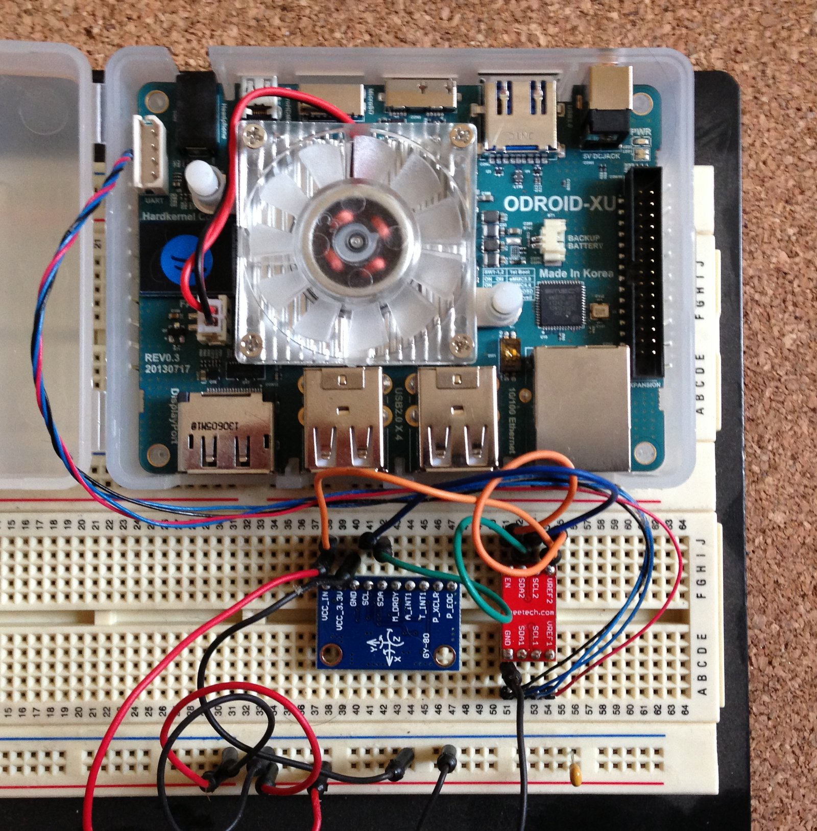
I decided to do some electronics and software testing before finishing building the second leg of my DARwIn-OP robot.
I wired my ODROID-XU with the GY-80 10DOF module using the I2C bus on the LCD connector (CON15) and a PCA9306 to adjust communication voltages.
ODROID-XU I2C Test Setup
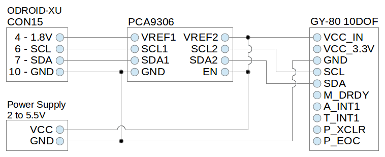
The following is the connection diagram tested:
I2C Test Diagram
This 10DOF can be powered from 2V to 5.5V (VCC_IN). Its sensors are internally powered at 3.3V, but according to this documentation its I2C interface is rated at VCC_IN, so the PCA9306 has to translate from ODROID-XU’s 1.8V to VCC_IN (and not to 3.3v).
This 10DOF has 4 I2C devices in the following addresses:
0x1E: 3-axis compass (HMC5883L chip)
0x69: 3-axis gyroscope (L3G4200D chip)
0x53: 3-axis accelerometer (ADXL345 chip)
0x77: pressure and temperature sensors (BMP085 chip)
With this small C program, the accelerometer chip can be query in order to detect it and verify the setup. I am currently testing Ubuntu Server 14.04 off the shelf on the ODROID-XU, which includes the GCC compiler by default.
Now that I have I2C communication running, I followed the chips documentations and some googled examples in order to write some draft C++ classes to read the 10DOF sensors. They are available in this Code Section in the SourceForge repository for cloning the DARwIn-OP Robot.
I could successfully test the 10DOF powering it (and the PCA9306) with 3.3V and 5V, but at 3.3V they draw 0.024A (or 0.079W) and at 5V they draw 0.085A (or 0.425W). So in my final DARwIn-OP design I will most probably include a 3.3V regulator to lower consumption.
The original DARwIn-OP Robot uses an on-board 1.6 GHz Intel Atom Z530 computer and a CM-730 ARM controller board. This controller board includes a 3-axis gyro, a 3-axis accelerometer and a Dynamixel bus to interface with the robot’s servos.
I intend to use an alternative electronics based on a more powerful ARM computer plus several peripherals. For the main computer, my current choice is the ODROID-XU which is a quad Cortex-A15 1.6GHz CPU with 2GB RAM.
Instead of using a controller board, I’ll be using a USB2AX to interface the Dynamixel servos and I’ll use I2C components for the gyroscope and accelerometer.
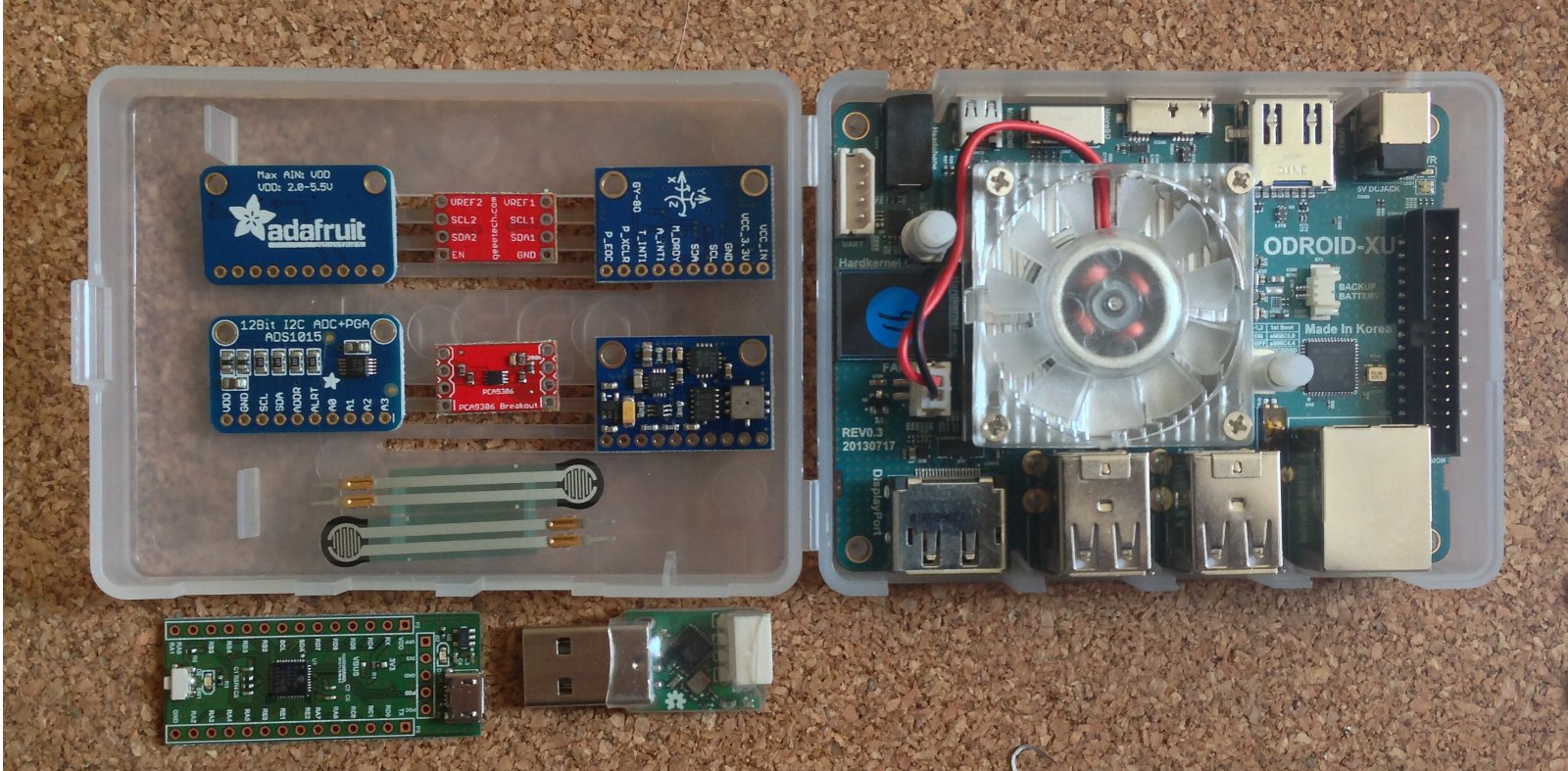
ODROID-XU and peripherals
On the picture are shown the components that I already got and that I’ll be testing:
I2C 12 bit 4 channels ADC (ADS1015 chip)
I2C voltage-level translator (PCA9306 chip)
I2C 10DOF with 3-axis gyro, 3-axis accelerometer, 3-axis compass, temperature and pressure sensors (L3G4200D, ADXL345, HMC5883L, BMP085 chips)
I’ll be using the native I2C interface I2C_0 that is available in the LCD connector (CON15) in the back of the ODROID-XU (the schematics are available through a customer email request to Hardkernel).
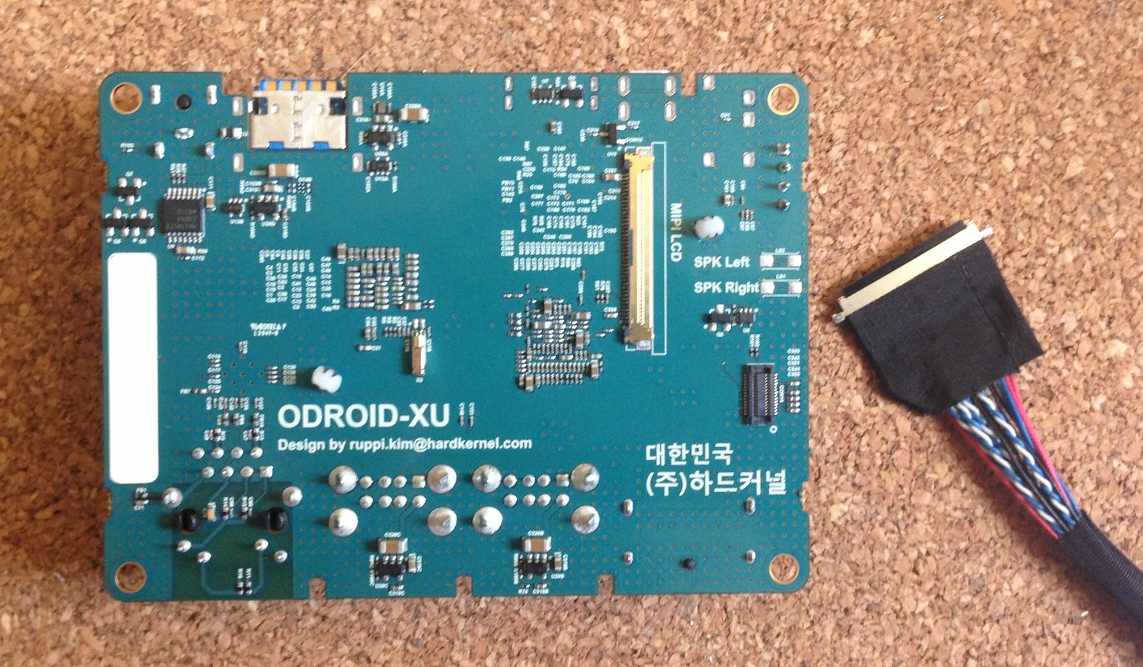
ODROID-XU LCD connector and cable
The LCD connector is an IPEX 40 pin with 0.5mm pitch. I got some a couple of cables from Ebay, but now I saw that Hardkernel (the maker of the ODROID) is also selling the cable. The pin configuration that I’ll be using for the I2C interface is:
4 – 1.8V
6 – SCL
7 – SDA
10 – GND
The ODROID-XU’s I2C interface is rated at 1.8V, so I’ll be using the PCA9306 to translate it to the rest of the I2C components which are rated at a higher voltage.
The DARwIn-OP requires a gyroscope and an accelerometer, but I am interested also in using the compass and the force sensors (through the AD converter) for a future version of the DARwIn-OP feet.