Debugged mill cuts

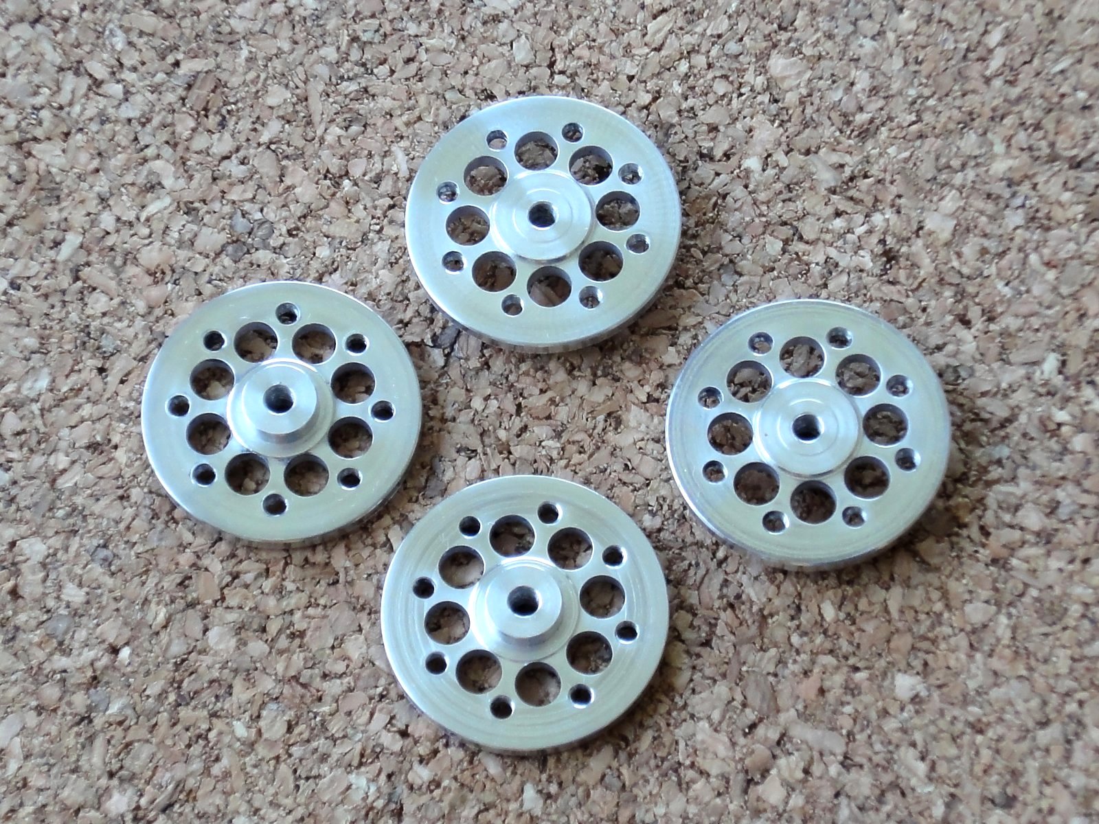
Continuing with my DARwIn-OP clone robot, I am now cutting the shoulder parts.

After most of the parts done, I am finally getting a better setup for cuts in my CNC Sherline mill.

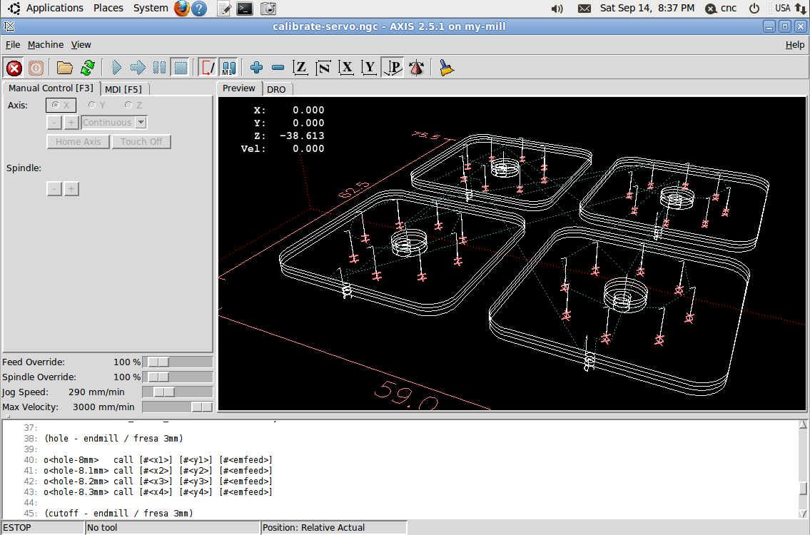
First I started fixing the aluminum sheets over small MDF board, cutting with 3mm endmills, a center drill, and several drills (1.6mm, 2.0mm, 2.05mm, 2.5mm, and 2.6mm), later I moved to a smaller 2.5mm endmill for better score’s finish. Following the DARwIn-OP Fabrication Manual, I placed checks on the cutoff path so the parts would not come loose. Later I replaced the MDF base board with an aluminum plate. Then I tested only using a single 1.5mm endmill for everything, but I didn’t like the surface finish and the holes weren’t perfect enough.

Now I think I have a better setup:

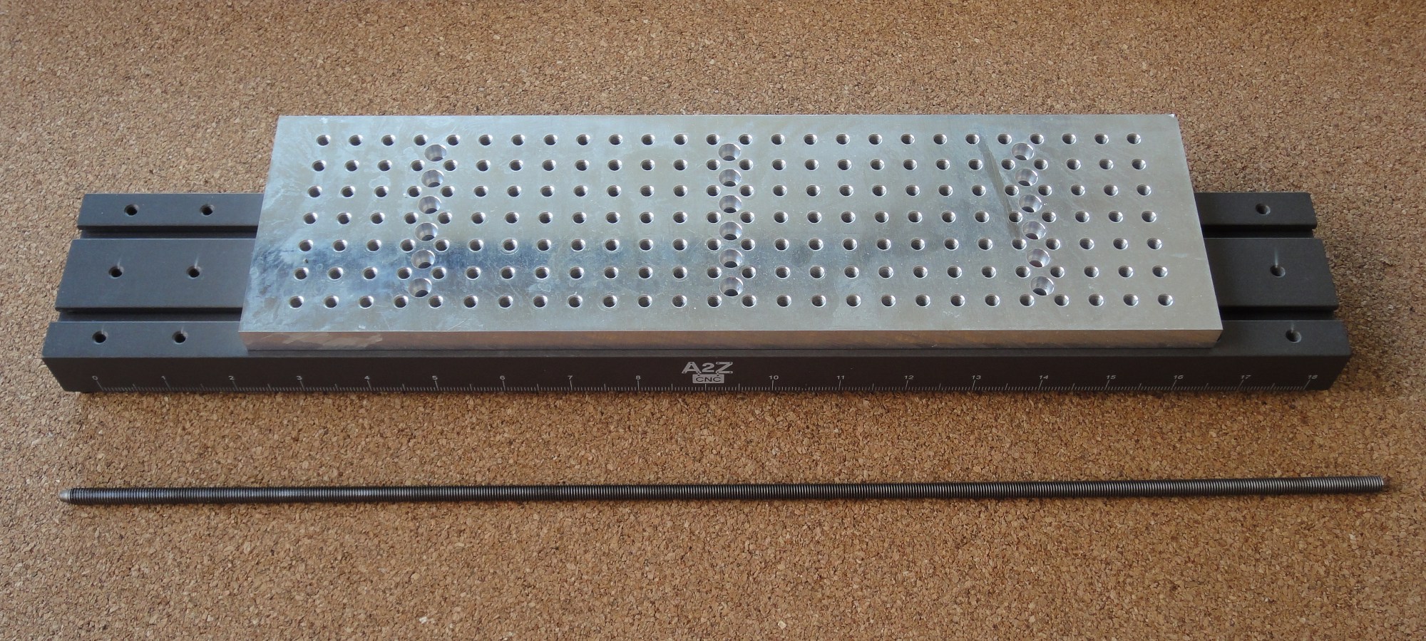
  • Following a friend’s setup, I replaced my mill’s aluminum matrix plate with a MDF board with the same size and attachment.
  • I fix the aluminum plates to the MDF board with several 2.5mm x 10mm screws around the parts to be cut. For this, I drill the MDF with a 2mm drill, 9mm deep. After several cuts, the MDF can easily be changed with another one.
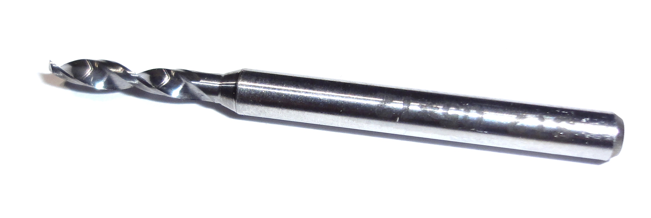
  • I went back to milling with a 2.5mm endmill (or 2mm endmill depending on the detail of the part, the Fabrication manual recommends a 3mm endmill, but some of the designs require 1mm radius cuts).
  • I went back to using drills of  size 1.6mm, 2.0mm, 2.05mm, 2.5mm, and 2.6mm. But since these are carbide drills with a wider (1/8″) shaft, I am not using a center drill any more to mark the holes. (After a few tests, I saw no hole displacements).

    Drill
    Drill
  • I am not leaving checks on the cutoff paths anymore. Now I screw the part to the MDF before doing a complete cutoff. I use some of the original holes of the part for this.
  • For any big slot that need to be emptied on a part, I mill it completely so no sizable aluminum bit that gets loose could break the endmill. If the slot is too big, then I would also place some screws on it so I don’t have to mill it all off.
  • Also, I replaced the Sherline mill headstock with an ER-16 model (from Sherline also). This allows for much easier tool changes, and ER-16 collets are available such as Techniks collets with very good accuracy (low TIR) which is important to keep small endmills well centered.
  • I upgraded the mill to 10k RPM (with a 10k RPM pulley set from Sherline).
  • I am cutting with the 2.5mm endmill at 5k RPM, 200mm/s speed, and 0.4mm depth of cut. For the 2mm endmill, I change the depth of cut to 0.25mm.
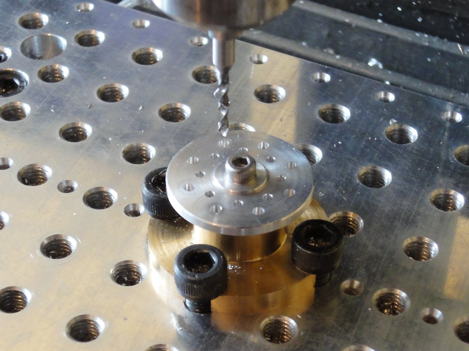
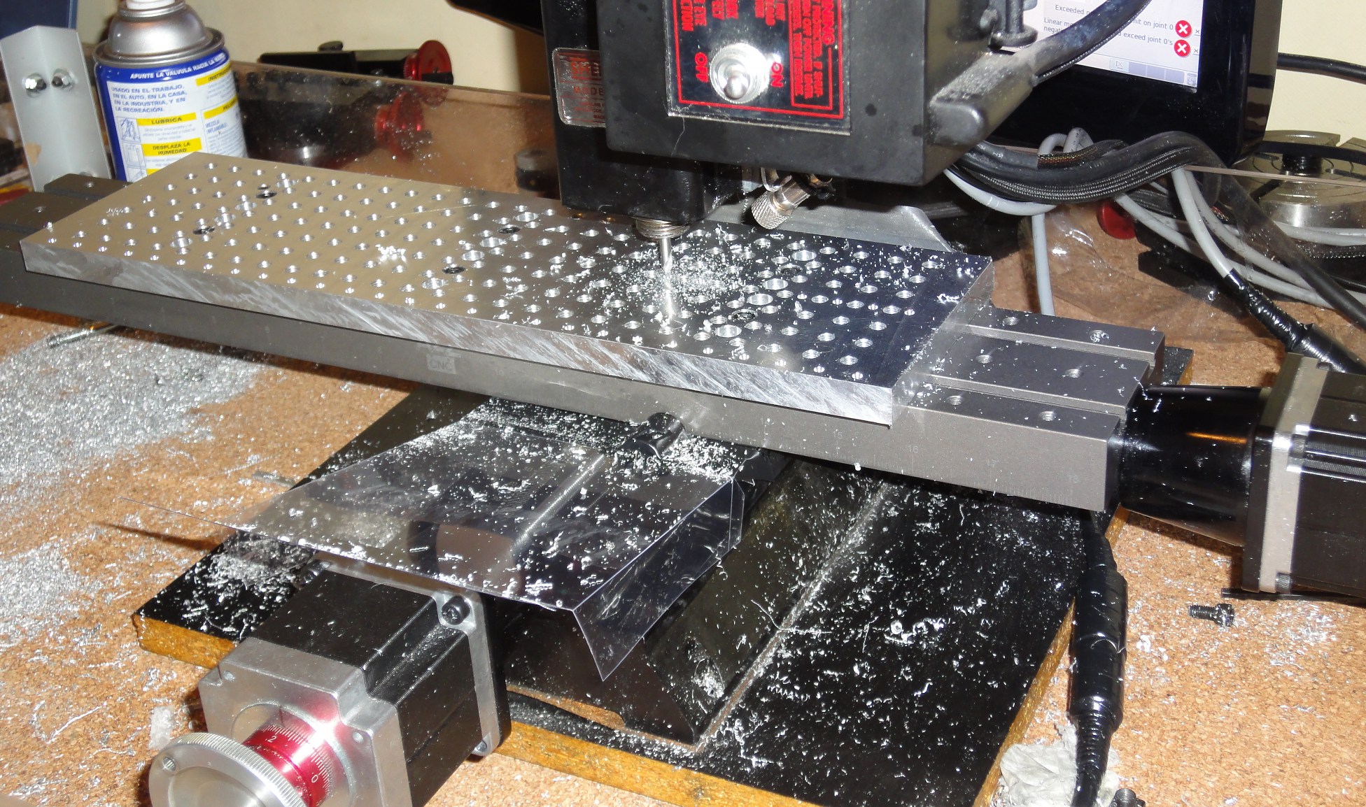
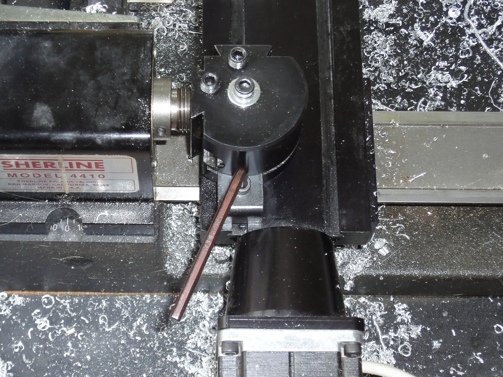
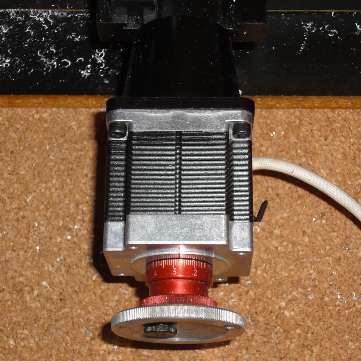
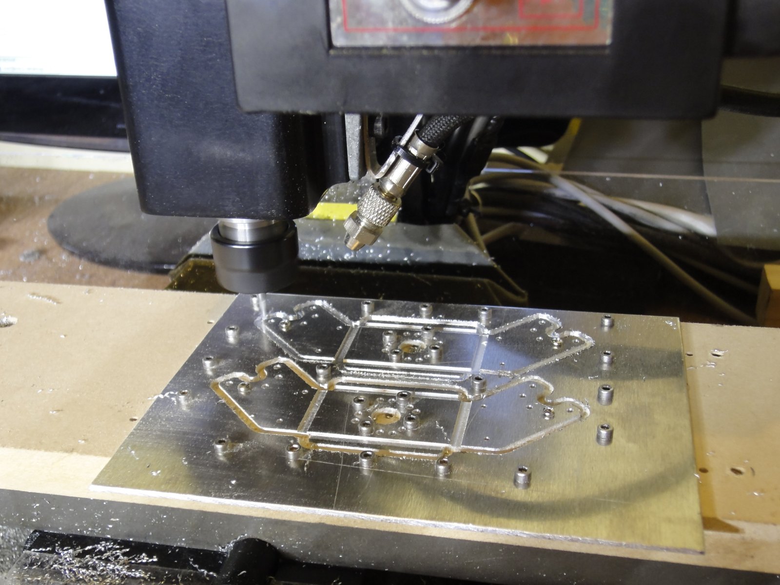
  • I don’t use any lubricant, only an air blower to keep the cutting area clean (see photo).

The following picture shows the setup while milling the last cutoff:

Cutting DARwIn-OP shoulders

The older gcode files I wrote don’t follow this setup, but can easily be updated.

Cutting Flange Bearings for my DARwIn-OP robot clone

I almost decided to buy the 4 Flange Bearings FR07_F101 needed for a DARwIn-OP clone. But it just took me one afternoon to cut them on the lathe and drill them on a mill.

Finishing a FR07_F101
Four FR07_F101
Four FR07_F101

I tested the assembly of a bearing joint as described in the DARwIn-OP Assembly Manual. I haven’t anodize the parts and it seems  I’ll have a hard time disassembling the joint, the bearing is very tight.

Bearing Joint Assembled

The gcode cut programs are in the Code Section and zipped in File Section in sourceforge repository for cloning the DARwIn-OP Robot.

Now I can continue testing the full assembly of a leg of my DARwIn-OP clone.

CNC Sherline Mill Extended Table Upgrade

I decided to upgrade my Sherline Mill. I got an extended 19″ X axis table from A2Z and a 14″ matrix plate from High Tech Systems. Sherline also has an extended table, but I wanted to try this brand because it is a little more taller and milling frames for a DARwIn-OP robot clone is a very low profile work and the endmills used are too short. The matrix table helps in height and supporting a 4″ wide work.

Extended Table and Matrix Plate

The matrix plate is quite nice, just one corner got scratched, probably on the trip to Chile. The extended table is quite long. To install it requires to adjust the gib on the base dovetail which took me hours, now I have a 360mm range on the X axis.

I drilled a new pattern of holes in the matrix plate to better hold aluminum plates for cutting DARwIn-OP’s frames.

New Hole Pattern
New Hole Pattern

The hole pattern has M2.5 threads. The holes are ½” apart to align to the preexisting pattern. I made 3 hole lines, one at the middle and one at 5/32″ from each border of the 4″ plate.

First lathe parts for my DARwIn-OP Robot Clone

Now that I am finished setting up my Sherline CNC lathe to cut my missing DARwIn-OP parts (FR07-F101, HN07-i101, and RX28-CAP), I am doing the first test cuts.

HN07-I101 and RX28-CAP
HN07-I101 and RX28-CAP (my cuts on left and original on right)

I manage to cut the HN07-I101 and RX28-CAP.  I have an original set that I bought, so I am able to compare, the ball-bearing fits tight enough. I still have to make the holes, but I’ll device some tools to use on the mill for this. Then I still have to polish and anodize.

I used some spare 20XX aluminum that I had, a 1″ bar for the HN07-I101 and a 5/8″ bar for the CAP, I am still waiting for some 6061 aluminum 15/16″ and 3/8″ bars to do the final pieces. The G-code cut programs are available on the Code section of my sourceforge project, they require a quick (or automated) change tool post with this setup of tools.

Sherline Lathe Quick Change Setup

So, to continue with my DARwIn-OP Robot Clone, I need to make a few parts on the Sherline lathe.

For this, a quick change setup is really practical.

Quick Change Tools Setup
Quick Change Tools Setup (updated)

Using quick change tools allows to calibrate each tool once. Later, when cutting parts, the tools can be easily swapped in a few seconds, settling back again to the same positions with minimal margin of error.

The basic tools I use are (updated):

  1. Right Hand Cutter (55° insert)
  2. Boring Cutter (for hole boring)
  3. Left Hand Cutter (55° insert for back face cutting)
  4. Cutoff Cutter (for cutting off the part from the stock metal)
  5. Left Hand Cutter (minimum radius tip for corners)
  6. Left Hand Cutter (in position for right facing)
  7. Right Hand Cutoff Cutter (tool #4 but calibrated for right and cutting)

The quick change tool post must be aligned specially for the cutoff cutter to be aligned when cutting. I use the headstock to do the alignment.

Quick Tool Post Alignment

For CNC operation, the tools have to be configured in LinuxCNC’s tool table. So the software can compensate for the offsets for each tool.

Tool Table Configuration

Several test cuts have to be made to properly calibrate the tools X and Z offset, also the tool nose diameter can be setup to compensate on diagonal cuts.

Anyway, using a lathe (and a CNC version) have to be done cautiously. A wrong move could hit a cutter or its holder with the metal block you intend to cut and the CNC software won’t notice, plus the quick change tool post will get misaligned and all the calibration will have to be done again. It is also good to follow some safety guidelines like always turning off the lathe before switching tools or drills.

Sherline Custom CNC Setup

I bought both a Sherline mill and a lathe a few years ago.

Sherline Mill
Sherline Mill
Sherline Lathe
Sherline Lathe

Right away I decided to add computer numerical control (CNC) by buying the hardware (stepper motors and mounts from Sherline) and save money by customizing the electronics.

Stepper Motor and Mount

There are some nice 3 and 4 axis stepper motor controllers available with the Toshiba TB6560AHQ chip, which is a PWM driver with microstepping capabilities and up to 3.5A capacity per phase. These controllers can be connected to a PC through a parallel port (which is preferred because of low latency) and cost less than 100 USD.

Stepper Controller
Stepper Controller

On a PC, LinuxCNC is an Ubuntu based Linux distribution (with an ISO installer) with real time extensions (needed to run the stepper motors smoothly) and CNC software to run G-code programs. It can be easily setup to use a parallel port stepper controller.

LinuxCNC
LinuxCNC

The original Sherline stepper motor is rated 2A and 3.2V. Most stepper motor controllers based on the Toshiba TB6560AHQ chip available in places like ebay are rated 3.5A but can be setup to 70%, 50% or 20%. So a 50% setup would give a would give me a 1.75A current level, which is close enough to the motor rating. Also a 24V and 8A power supply is enough to power the controller, a much higher voltage than the motor’s rating is needed to step it fast by forcing a current change in the motor’s coils at high voltage.

Anyway, by checking the Toshiba TB6560AHQ datasheet, I noticed that the maximum current level is defined by a couple of resistance (R) connected to pins 11 and 14 (one for each motor phase). The maximum current is set to 0.5V/R. These resistances have to withstand the maximum current at 0.5V, that means 1.75W for a 3.5A setup. They should be big enough for this power rating. By looking at my 4 axis controller circuit board, no big resistance are visible. So I disassemble the board (which has each driver screwed for power dissipation) and I looked on the lower side, finding 2 sets of 3 big resistances per driver.

Stepper controller current sensing resistances

These resistances seem to be in a parallel configuration and have values of 1Ω, 0.51Ω, and 0.33Ω. The equivalent resistance is then 0.167Ω, which means a 3A max current (my controller was documented to be rated 3.5A which seems not to be the case). The 50% configuration that I was considering would give me a 1.5A setup, much lower than the 2A motor rating.

Now, if the controller had only the 1Ω and the 0.33Ω resistances, that would be equivalent to 0.248Ω, which means a 2.02A max current, close enough to the motor rating. So I only have to remove the 0.51 Ω resistances and set the controller to 100%.

Stepper Controller modified for 2A max current

Somebody did a good design with these 3 resistances in parallel, you can setup a maximum current of 0.5A, 1A, 1.5A, 2A, or 2.5A by removing 1 or 2 resistances.