Hacer la primera pierna para mi clon del robot DARwIn-OP fue bastante trabajo, especialmente en medir los modelos 2D, luego descartarlos y retomar los modelos 3D para trasladarlos a G-code, además de probar formas más eficientes de trabajar con la fresadora.
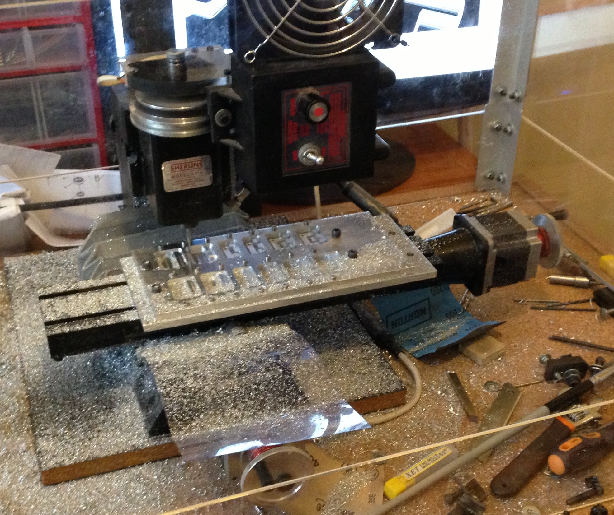
Ahora, cortar la segunda pierna fue mucho más fácil.
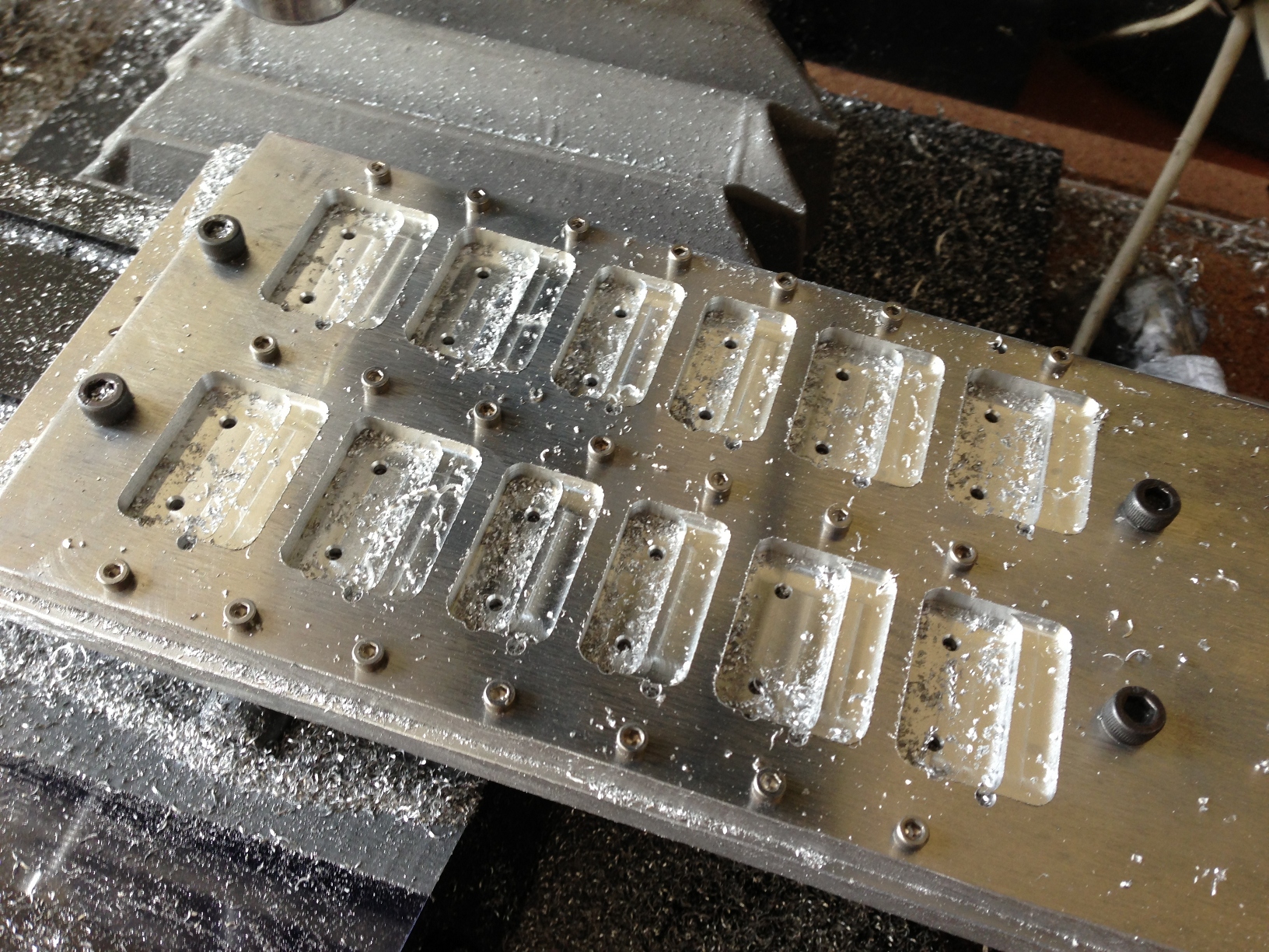
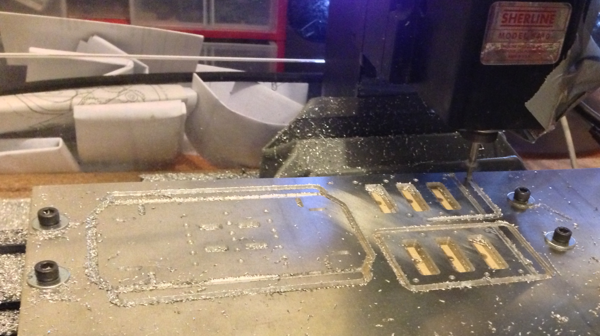
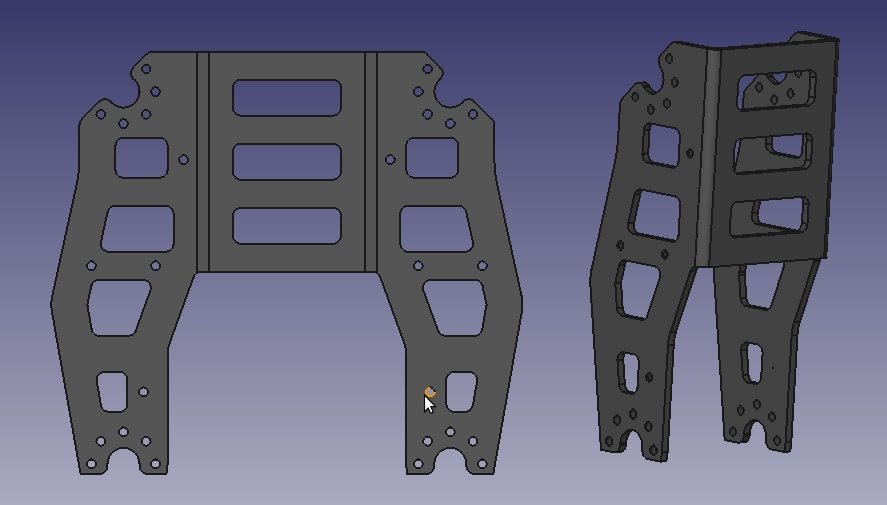
Cambié la pieza de de la ‘rodilla’, mi primera versión tenía un doblez en la parte baja, pero lo eliminé del diseño para permitir que mi clon de DARwIn-OP tenga el mismo rango de movimiento en las articulaciones que el robot original. También, mi primera tanda de piezas FR07-S101 tenían 4 agujeros faltantes (se ve en la foto, por suerte no son usados en el robot DARwIn-OP).
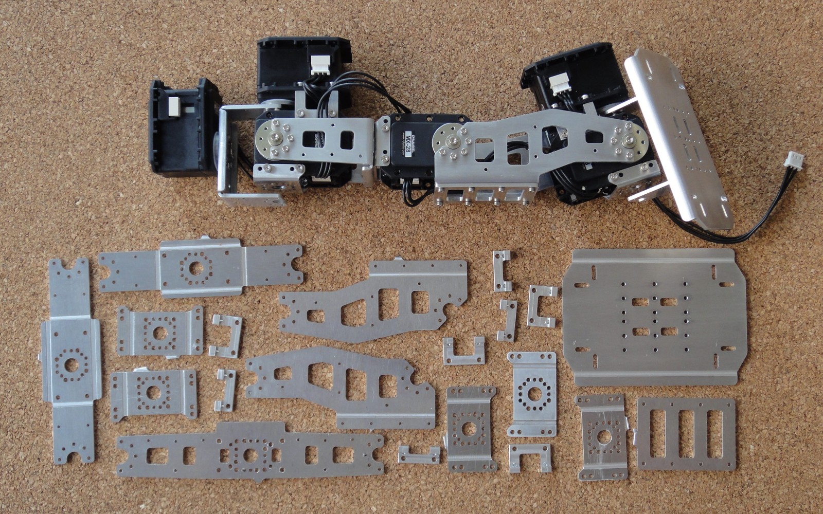
Todavía tengo que limar y doblar las piezas, pero primero voy a tratar de hacer algunos bloques de aluminio que me ayuden con el doblado, el Manual de Fabricación muestra ejemplos de esto en el apéndice.
Mientras tanto, voy a comprar unas barras de aluminio 6061 de 1″ y 3/8″ para tornear las piezas FR07-F101, HN07-i101 y RX28-CAP. También tengo que calibrar las cuchillas de cambio rápido de mi torno, lo que toma tiempo, pero una vez hecho, permite cortar diseños complejos bastante fácilmente, haré un post de esto más adelante.