
So far, I haven’t powered up any servos. They can be connected in a daisy chain 3-wire TTL bus (ground, power, and TTL communication). Each Dynamixel MX-28T has an internal PID controller and has several configurable parameters and feedback data.
I’ll do the configuration of a few Dynamixel MX-28T servos, each should be setup with its ID and baud rate at 1Mbps to be used in the DARwIn-OP clone. The ID for each servo should be from 1 to 20 depending on its location in the robot, as listed in the DARwIn-OP_Actuator ID doc or the DARwIn OP Assembly Manual doc. They come factory programmed with ID = 1 and 57142 bps baud rate and it won’t work to daisy chain 2 servos with the same ID.
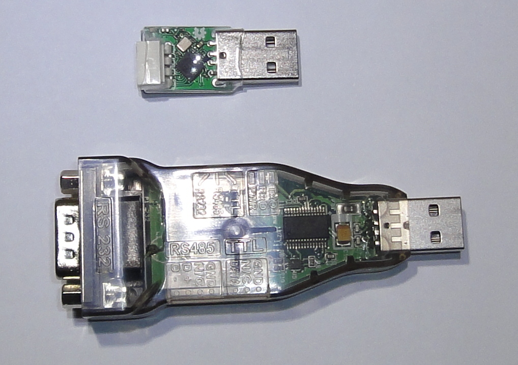
I got a Power Hub for the Dynamixel TTL bus and wires. The wiring is simple: power supply (12V) to the hub, one connection to a servo, and one connection to the USB2Dynamixel USB adapter (switched to TTL mode on the side).
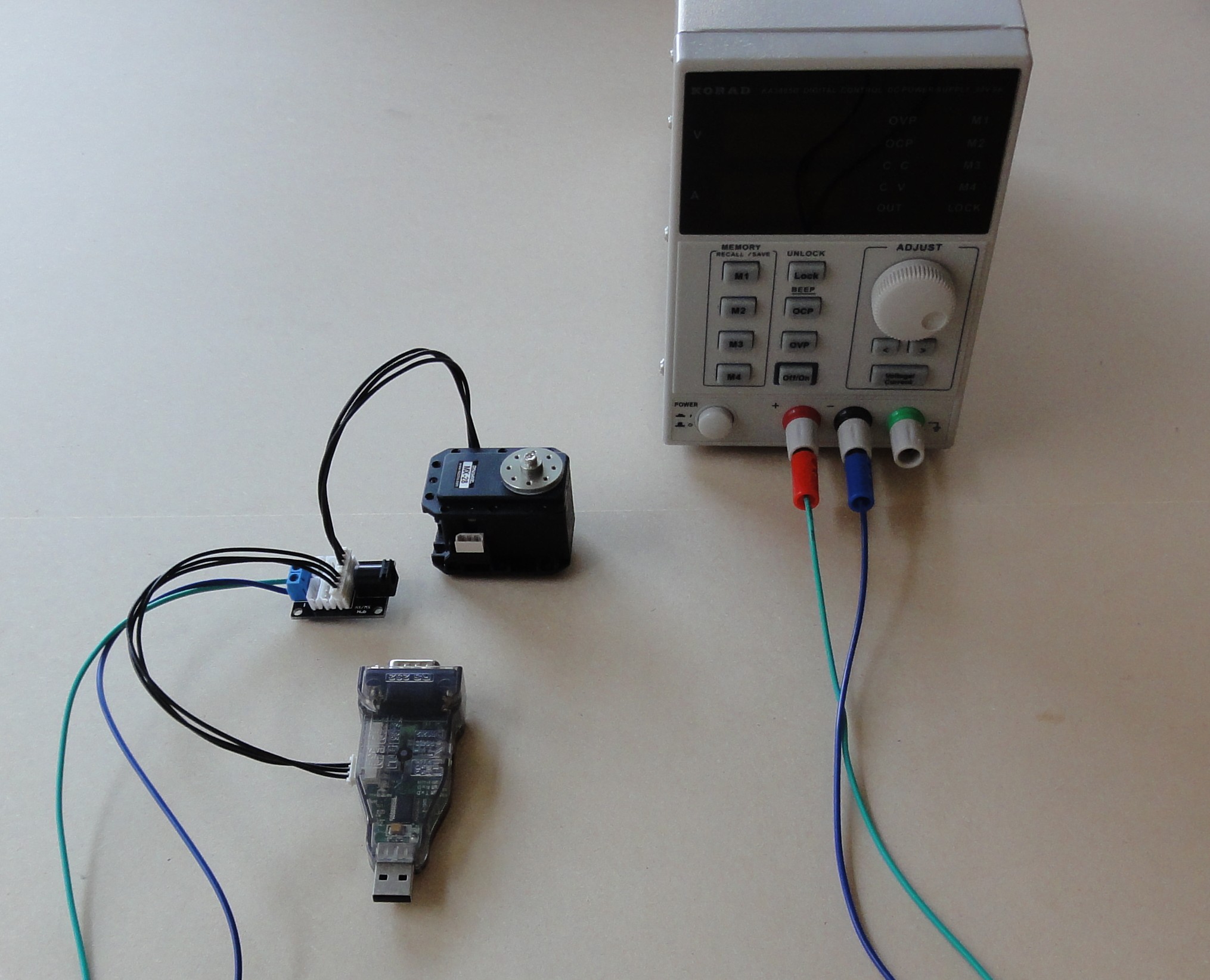
I have a nice enough digital power supply with over current protection and amp meter which is helpful to have an idea of the power consumption of the servos when idle and when applying torque.
The recommendations I found tells first to connect all the wires, then to plug the USB adapter to the PC, then to power up the power supply. Reverse these steps to shut down. Setting the power supply at 12V and 1A OCP is more than enough to tests one MX-28T servo.
The Robotis RoboPlus software can be used to configure a servo. It contains several tools, in particular the Dynamixel Wizard. It is available for download and runs only on Windows, even though the DARwIn-OP software runs on Ubuntu Linux.
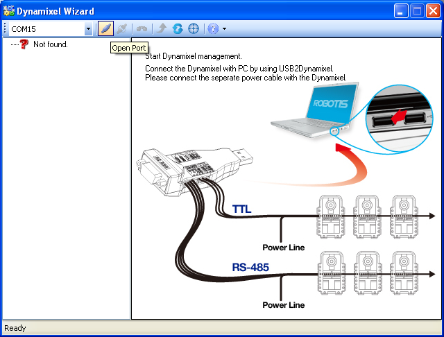
Installing the RoboPlus software is easy and it silently installs the USB2Dynamixel driver too. Once installed you can plug in the USB2Dynamixel and check on the Windows Device Manager which COM port it got assigned to. Then you can run the Dynamixel Wizard software, select the assigned COM port in the left combobox, and press the ‘connect’ icon.
So after pressing the ‘connect’ icon, you are presented in the right with options for bps (2 rows, 1000000 bps and 57142 bps, this allows to find servos in both Baud Rates) and search type (the default Basic Search is ok).
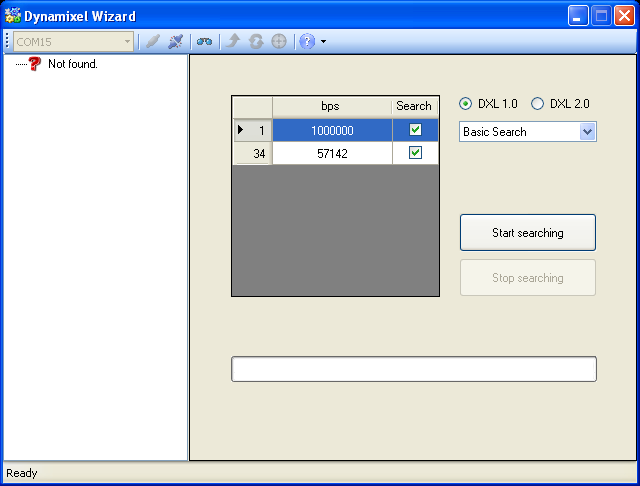
We do a search and the software starts scanning each Baud Rate from ID 1 to 253. This takes a few seconds and the servo (or servos) connected should appear in the left side in a tree view.
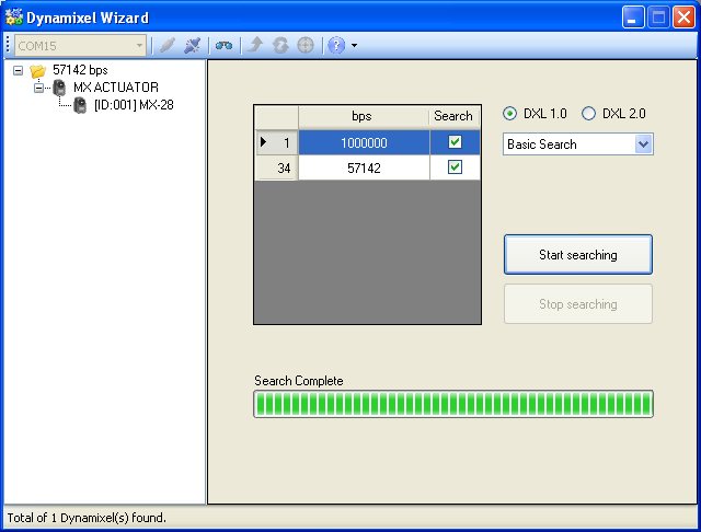
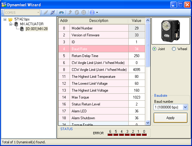
Clicking the servo will change the right panel with a table of all the registers of the servo. Some registers are RW and some are RO as described in the MX-28T specifications. The DARwIn-OP clone uses the servo in Joint Mode (as opposed to Wheel Mode for a car) . Here we can:
- Change register 3 (ID) (clicking it and setting it to the desired value on the right).
- Change register 4 (Baud Rate) to 1 (which means 1000000 pbs).
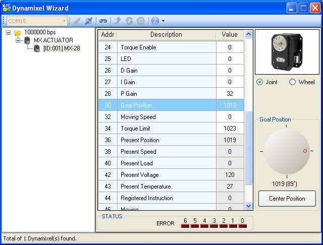
Also we can test the servo by:
- Reading register 36 (Present Position) while we manually turn the servo. The value should change while turning.
- Moving the servo by changing the value of register 30 (Goal Position). Once you write a goal position, the servo also remains activate and will try to keep the goal position. With a brand new servo’s default factory settings, is quit impossible to manually turn an activated servo. If you try and you can measure the current spiking as the servo tries to counteract you.
Latter I want to try the USB2AX adapter, which is much smaller than the USB2Dynamixel adapter, but only works at 1 Mbps (which is anyway best to lower delays) and has only a TTL bus (just the case for these servos).
Once several servos are configured with different IDs, they can be daisy chained and connected together to a PC or used in the DARwIn-OP clone.