
Now that the first proof of concept was done with the first test cut, I am continuing with the DARwIn-OP frame parts bottom up starting with one leg.
Since my Sherline mill can manage a surface about 200x100mm. I sliced out my aluminum sheets in smaller pieces, after the first few cuts I ended up reducing the size to 150x100mm and 200x100mm pieces depending on the size of the parts to cut.
The foot is the FR07_E160 frame. The Fabrication Manual lists this part as 1.5mm thick on page 8. But the 2D and 3D model files are consistent with a 2mm thick part. I believe the manual is the one mistaken.
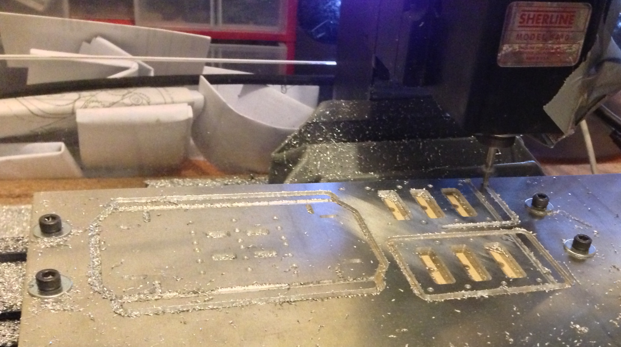
The first foot was cut over a 9mm wood plate. I later changed to using an 1/4″ aluminum plate as this is much more sturdy, I’ll go on this latter. The tools used are:
- Centerdrill #1
- drill 2mm (since at the moment I didn’t have a 2.05mm drill yet, the holes must all be 2.5mm tapped).
- endmill 2.5mm for the slots (the thinner ones mesure 2.6mm wide on the model).
- endmill 3mm for the cut-off. I latter stopped using the 3mm endmill as this requires an extra tool change (My mill does not a fancy automatic tool change).
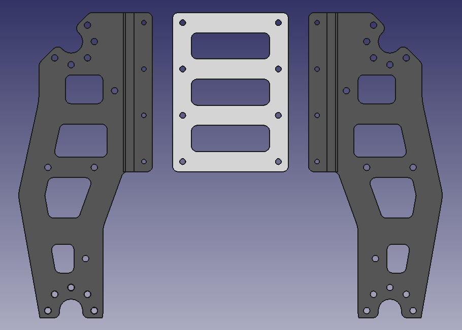
With the foot I also cut a couple of ‘knees’. The DARwIn-OP may seem to be a small robot in pictures, considering it is about 45cm high (1.5 feet). But some frame parts are not as small as I imagined initially. The lower leg part FR07_H133 is about 118x106mm before bending. Considering also the endmill width, the mill is short in about 10 millimeters in its shorter Y axis.
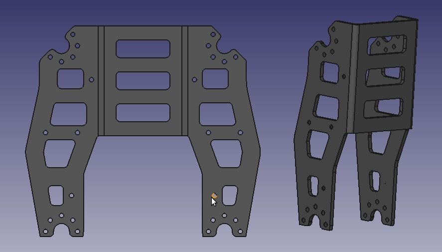
So I redesigned this part in 3 parts to be screwed together. Here are the STEP Files. The middle part was cut with the foot (though I changed the design after the cut).
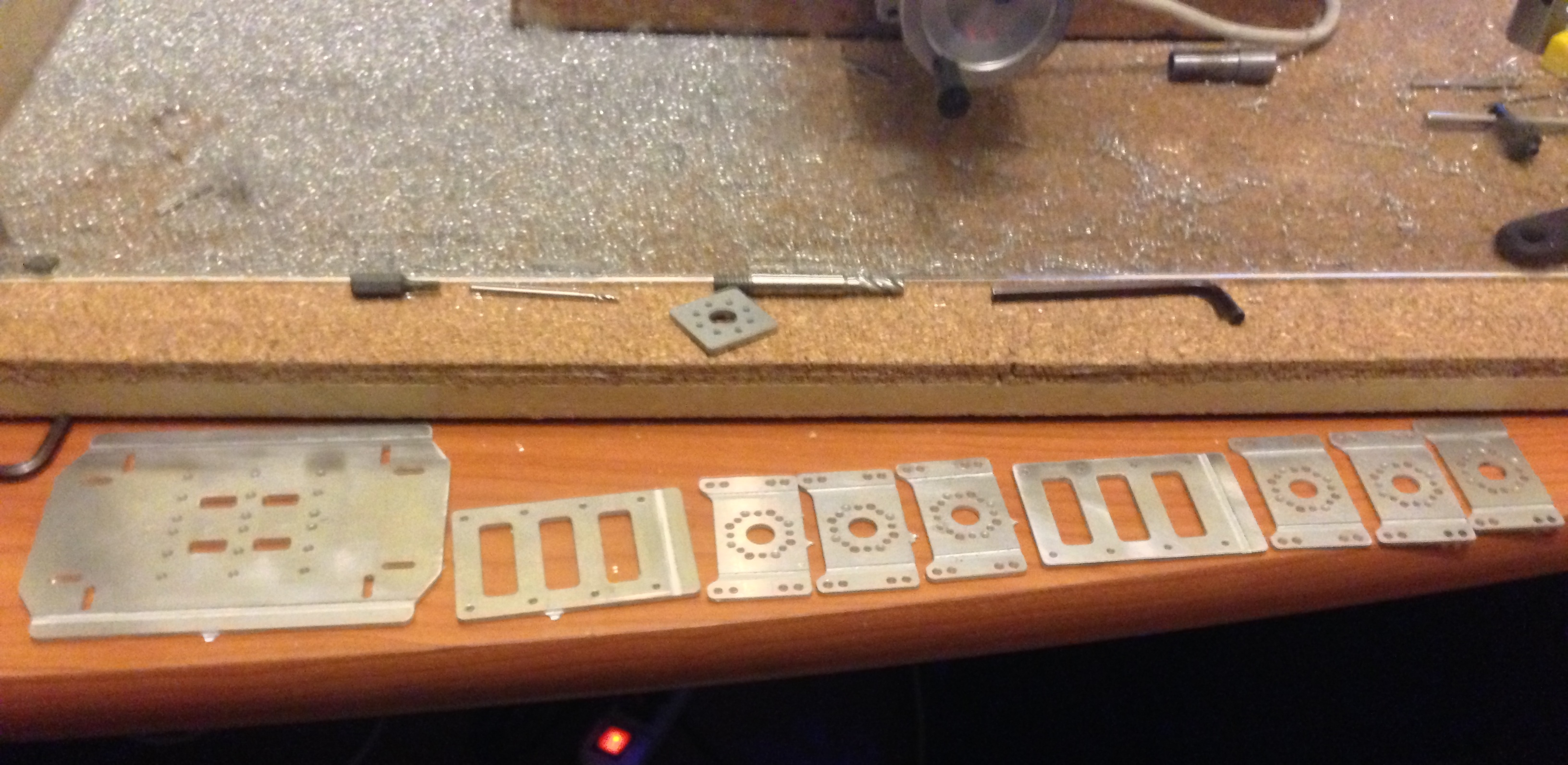
I continued with the FR07_S101 with is an actuator mount. This is designed in 1.5mm aluminum. I cut 6 parts simultaneously (enough for the whole robot).
Now the bending…
The DARwIn OP Fabrication Manual explains several methods for bending. This is the best part, because I learned ways to design parts beside just milling a solid block of metal which is time and material consuming. I don’t have a big bending machine which is the first method described. Instead, I got a mallet (like a rubber hammer so no scratching the metal) and a seamer.
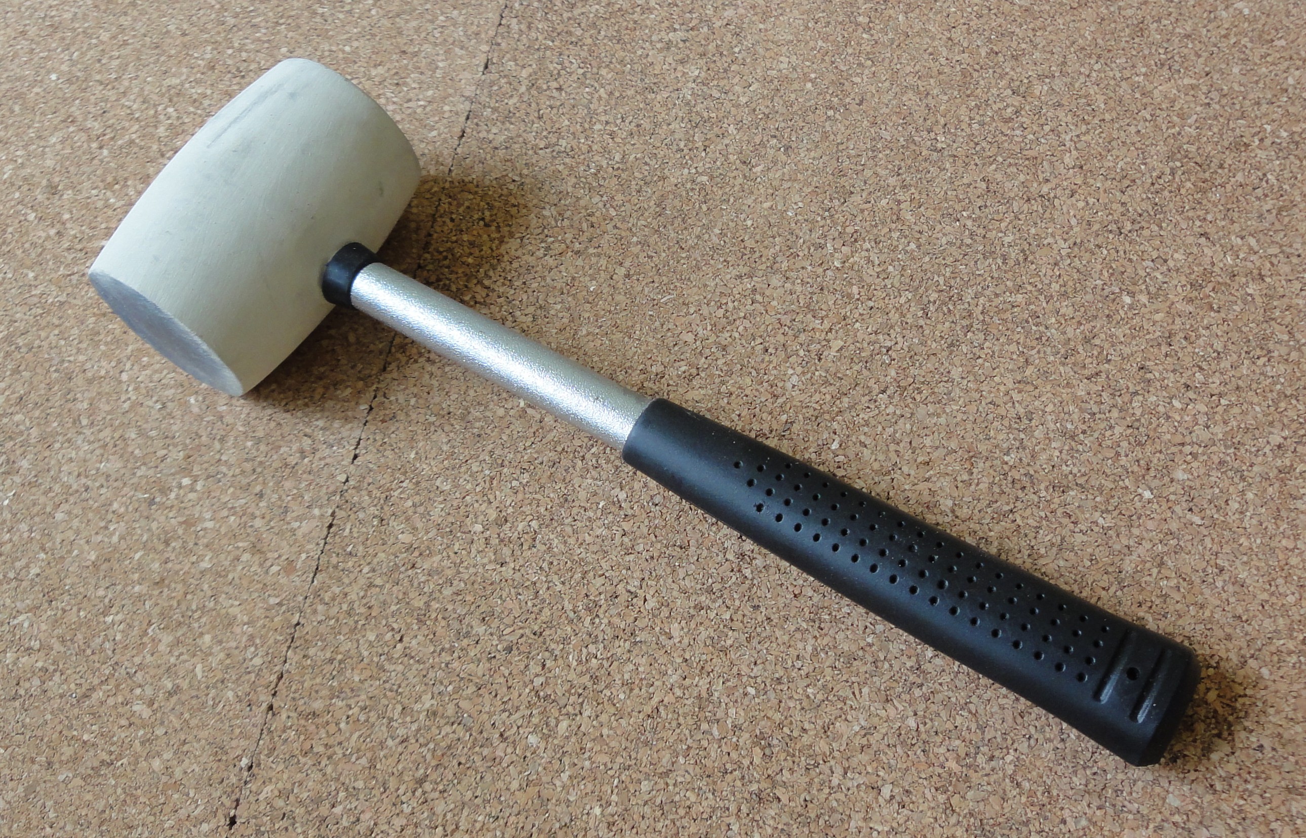
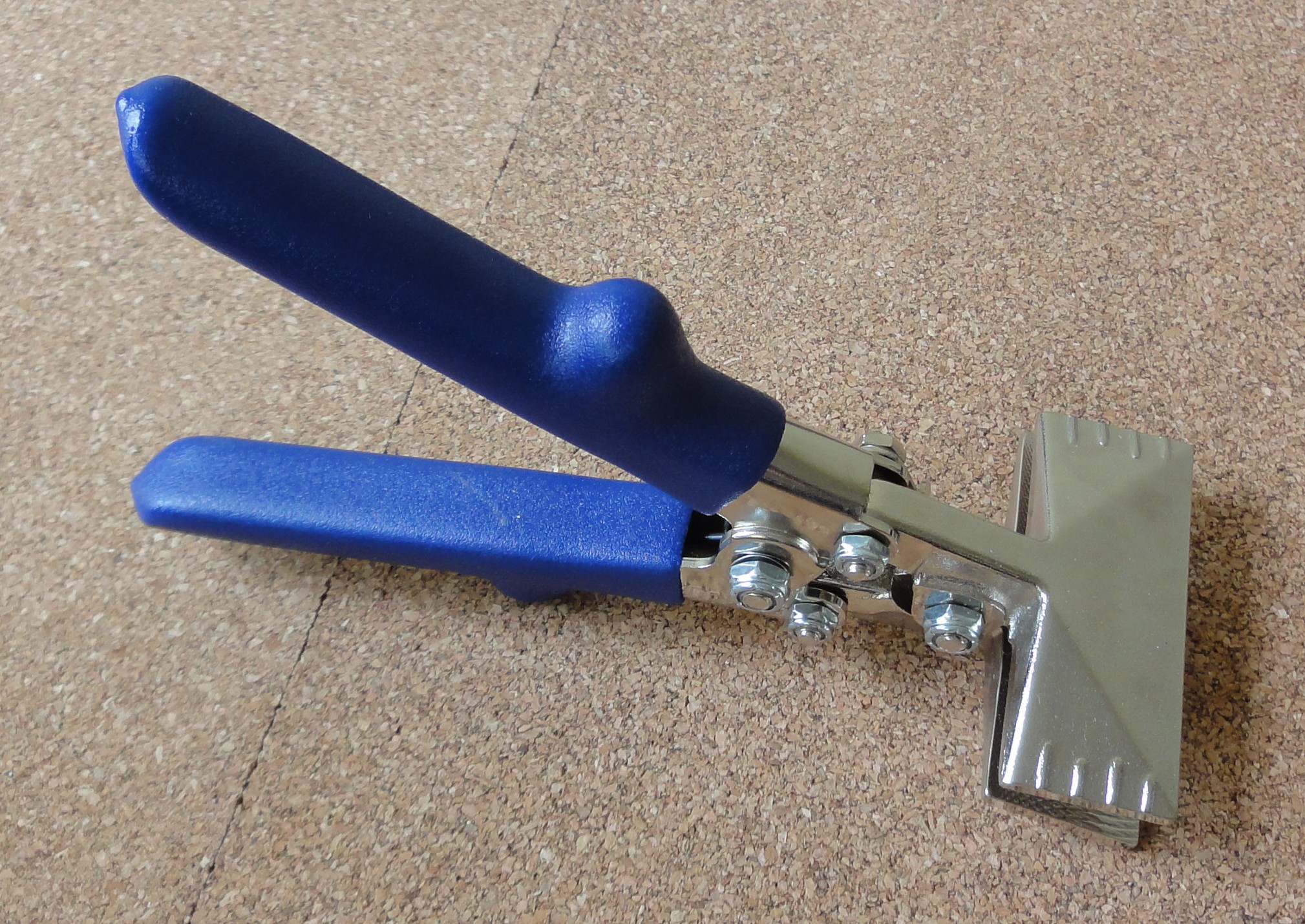
For bending I got a 4″ vise. Big frames like the foot requires a strong vise to bend.
After a few attempts, you start getting the feeling on how to do it right. With the seamer you have to be careful to bend symmetrically. With the mallet, you have to use hit it with a hammer gently all over near the bending axis.
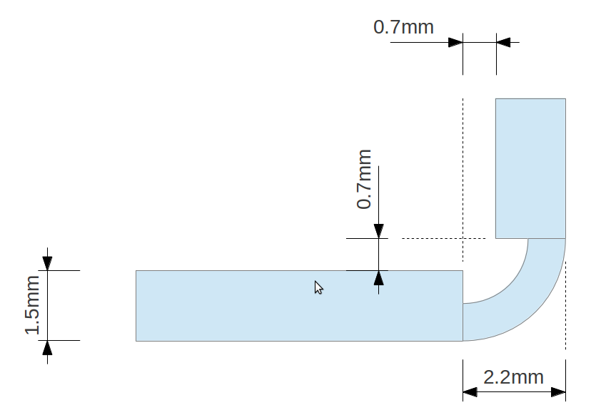
BUT… I manage to bend a FR07_S101 (actuator mount) with a seemly even bend. But this frame would not fit the Dynamixel MX-28T as expected (see Dimensions). The servo requires the frame to have a 30mm gap, but the frame ended up having a nearly 29mm gap. This is a 1mm error! I check the parts I made against the 2D models and they have a perfect match. The milling error is actually less than 0.1mm. So how did I ended up with a 1mm error?
To guide the bending, a score is milled to ease each bend. After checking the 2D model for the FR07_S101, the scores for bending are too close together, they are separated side to side by 27.563mm. The part requires to have 30mm separation between the sides, giving a difference of 2.437mm.
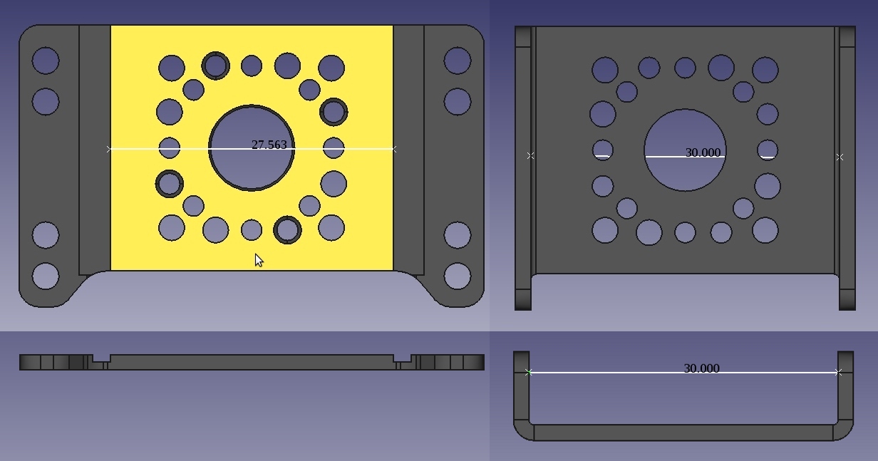
After bending, each bend adds about 0.7mm between the border of the score to the side. For the FR07_S101 frame, this accounts for 1.4mm and not 2.437mm as the models suggest.
From the bright side. I now have several useless parts to really test bending and anodizing without worrying if I screw it up.
The problem in the 2D models is not only that the scores are misplaced by about 0.5mm each, the whole model is also short by about 1mm in each side. So the FR07_S101 2D model is short by about 0.5mm on each side of a score. And this is happening on all the models I have been translating to G-code. The frames made of 2mm aluminum also have the same problem. Maybe if the parts were bent the other way around you could end up with the correct dimensions, but from pictures and instructions in the Fabrication Manual it is not the case.
I have found no problems in the 3D models, so I am rewriting the G-code programs by using them as the source of the design instead of the 2D models.
Have you been able to examine a production DARwin-OP to determine if the sheet metal is scored as described in the documentation?
I haven’t seen any DARwIn-OP in person, I haven’t even heard of any in my country (Chile).
Robotis does sell some of the frames used on the DARwIn-OP (at least the common ones not specific to this robot) but I haven’t bought any. From a few hires pictures on internet, they appear to be scored.
Anyway, I guess without the scoring it would be more difficult to bend properly. The scores serve as guide while bending and it is important to bend at the correct place and alignment (it is already difficult with the scores, I can’t imagine without them).