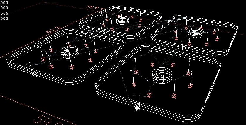
Many frame parts of the DARwIn-OP have a kind of repeating pattern where the servo horn hooks up. To get this pattern right will help on the G-code of several frames.
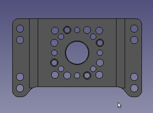
The frame requires an 8mm hole and eight 2mm holes around evenly spaced in a 16 mm diameter circle. Note also, that in the pattern there are 4 holes (2.05mm) a bit rotated that will be tapped for 2.5mm screws while there are also 4 holes (2.5mm) a bit rotated the other way around, this is used to screw 2 frames together. Looking at the FR07-H132 frame’s 2D model, it has this pattern flipped over. I think it is a mistake in the 2D file.
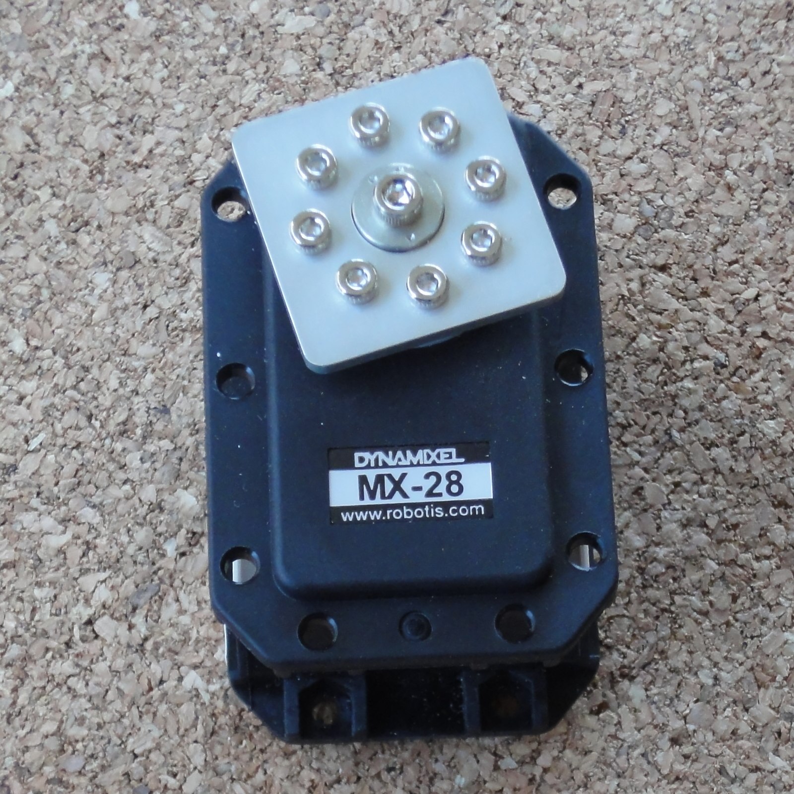
I got the aluminum sheets, the carbide 3 flute aluminum endmills, a couple of Dynamixel MX-28T servos with horns, and tap sets for 2mm and 2.5mm. I also bought a couple of FR07-I101 Bearing idler sets as samples.
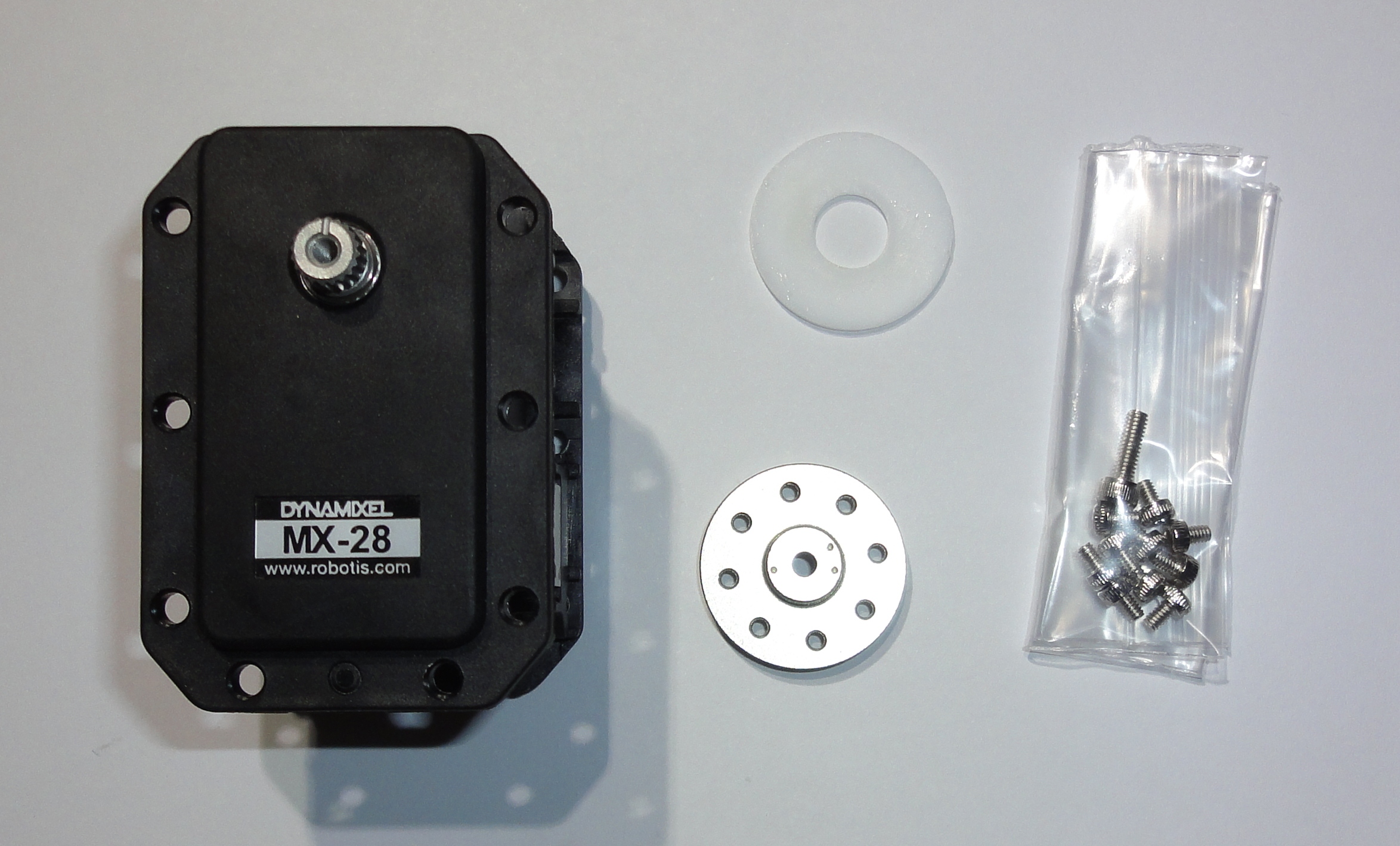
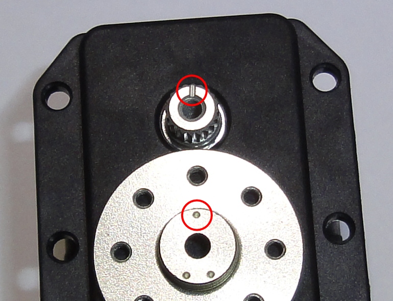
The horn has eight taped holes for 2mm screws (included) in a circle that match the repeating design pattern. The horn does not come installed, which is done with a 2.5mm hex screw (included) and this has to be done carefully since the horn has to be aligned with the shaft on the servo. Both have marks to do this. Once the horn is most of the way plugged in, it gets quite tight and it can get really difficult to get it back out.
So the first thing should be to make some trials on how much the 8mm hole should be 8mm so the horn can fit tight (so I don’t end up with frames that don’t fit the servos or are way too loose). For this I designed a few 24x24mm test square pieces with the eight 2mm holes and a the center hole varying from 8mm up in 0.1mm increments. the center hole is done with the 3mm endmill in a circular motion, so minimizing the mill’s backlash is important.
I ran the test cuts with feed speeds at 60mm/minute for the 3mm endmill and 30mm/minute for the drills. I did a first pass with a centerdrill #1, then a pass with a 2mm drill and then a final pass with a 3mm endmill.
The G-code files are in this archive: calibrate-servo.zip. the main G-code file is calibrate-servo.ngc.
I also tested polishing and anodizing the pieces. I used some silver polisher I found, works well but it tends to dry easily and then it is hard to take of. The anodizing process tested was a Type II anodizing with 12A/Ft² for 1 hour at 21°C in battery acid diluted 50% and no color dye.
The 8.1mm hole piece had the best fit with the servo horn, and the anodizing locks fine and scratch resistant. The eight 2mm hex screws fit perfectly.
I am thinking in buying some real aluminum polishing kit and also some aluminum color dye to test it out. Surely I’ll have plenty of ruined parts to get some practice. Anyway I’ll do any final anodizing after winter (in the southern hemisphere) so it is easier to keep the acid temperature over 19°C outside.