Probando el I2C del ODROID-XU

Decidí hacer algunas pruebas de electrónica y software antes de terminar de fabricar la segunda pierna de mi clon del robot DARwIn-OP.

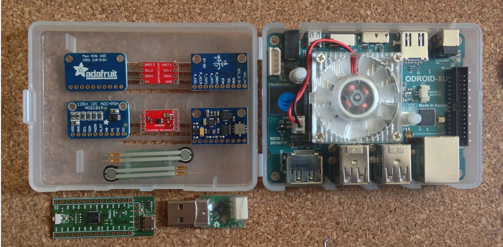
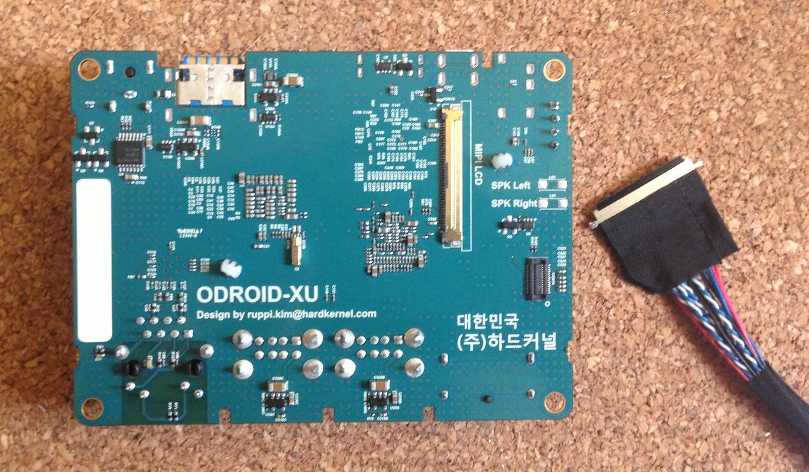
Conecté mi ODROID-XU con el módulo 10DOF GY-80 usando el bus I2C del conector LCD y un PCA9306 para ajustar voltages de la comunicación.

Setup de Prueba de I2C con ODROID-XU

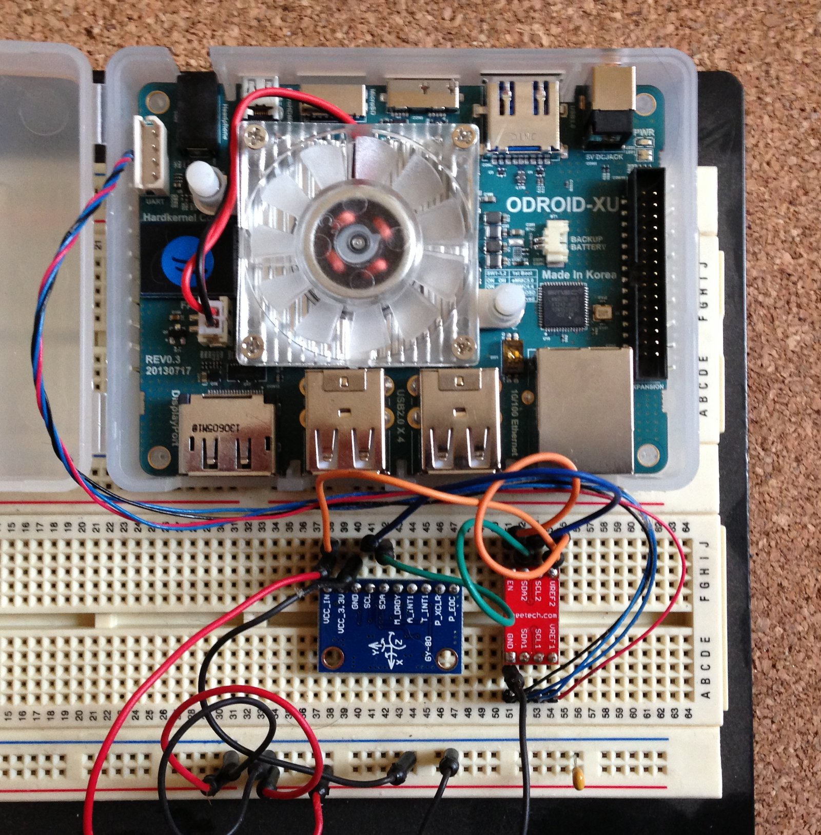
El siguiente es el diagrama de interconexión probado:

Diagrama de Prueba I2C

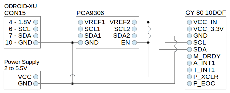
Este 10DOF puede energizarse desde 2V hasta 5.5V (VDD). Sus sensores están alimentados internamente a 3.3V, pero según esta documentación su interfáz I2C está ajustada a VDD, por lo que el PCA9306 tiene que traducir entre los 1.8V del ODROID-XU y VDD (y no 3.3V).

Este 10DOF tiene 4 dispositivos I2C con las siguientes direcciones:

  • 0x1E: compás de 3 ejes (chip HMC5883L)
  • 0x69: giroscopio de 3 ejes (chip L3G4200D)
  • 0x53: acelerómetro de 3 ejes (chip ADXL345)
  • 0x77: sensores de presión y temperatura (chip BMP085)

Con este pequeño programa, se puede consultar el chip del acelerómetro para detectarlo y verificar el setup. Actualmente estoy probando Ubuntu Server 14.04 de paquete en el ODROID-XU, el que incluye el compilador GCC por defecto.

Ahora que tengo la comunicación I2C funcionando, seguí la documentación de los chips y ejemplos en Internet para escribir un borrador de clases C++ para leer los sensores del 10DOF. Están disponibles en esta Sección de Código en el repositorio SourceForge para clonar el Robot DARwIn-OP.

Probé en forma exitosa el 10DOF energizándolo (junto al PCA9306) con 3.3V y 5V, pero a 3.3V consumen 0.024A (o 0.079W) y a 5V consumen 0.085A (o 0.425W). Así que en mi diseño final para el DARwIn-OP probablemente incluya un regulador de 3.3W para disminuir el consumo.

ODROID-XU I2C Testing

I decided to do some electronics and software testing before finishing building the second leg of my DARwIn-OP robot.

I wired my ODROID-XU with the GY-80 10DOF module using the I2C bus on the LCD connector (CON15) and a PCA9306 to adjust communication voltages.

ODROID-XU I2C Test Setup

The following is the connection diagram tested:

I2C Test Diagram
I2C Test Diagram

This 10DOF can be powered from 2V to 5.5V (VCC_IN). Its sensors are internally powered at 3.3V, but according to this documentation its I2C interface is rated at VCC_IN, so the PCA9306 has to translate from ODROID-XU’s 1.8V to VCC_IN (and not to 3.3v).

This 10DOF has 4 I2C devices in the following addresses:

  • 0x1E: 3-axis compass (HMC5883L chip)
  • 0x69: 3-axis gyroscope (L3G4200D chip)
  • 0x53: 3-axis accelerometer (ADXL345 chip)
  • 0x77: pressure and temperature sensors (BMP085 chip)

With this small C program, the accelerometer chip can be query in order to detect it and verify the setup. I am currently testing Ubuntu Server 14.04 off the shelf on the ODROID-XU, which includes the GCC compiler by default.

Now that I have I2C communication running, I followed the chips documentations and some googled examples in order to write some draft C++ classes to read the 10DOF sensors. They are available in this Code Section in the SourceForge repository for cloning the DARwIn-OP Robot.

I could successfully test the 10DOF powering it (and the PCA9306) with 3.3V and 5V, but at 3.3V they draw 0.024A (or 0.079W) and at 5V they draw 0.085A (or 0.425W). So in my final DARwIn-OP design I will most probably include a 3.3V regulator to lower consumption.

Periféricos del clon de DARwIn-OP

El robot original DARwIn-OP usa un computador Intel Atom Z530 de 1.6 GHz y un controlador ARM CM-730. Este controlador incluye un giroscopio de 3 ejes, un acelerómetro de 3 ejes y un bus Dynamixel para conectar los servos del robot.

Por mi parte, pretendo usar una electrónica alternativa basada en un computador ARM más poderoso (y barato). Para el computador principal, mi candidato es el ODROID-XU que es un quad Cortex-A15 1.6GHz con 2GB de RAM.

En vez del controlador, usaré un USB2AX para conectar los servos Dynamixel y varios componentes I2C para el giroscopio y acelerómetro.

odroidxu-peripherals
ODROID-XU y periféricos

En la imagen se muestran los componentes que ya tengo que estaré probando:

  • Conversor ADC I2C de 12 bit y 4 canales (chip ADS1015)
  • Traductor de voltaje I2C (chip PCA9306)
  • un multi componente I2C 10DOF con sensores de giroscopio de 3 ejes, acelerómetro de 3 ejes, compás de 3 ejes, temperaura y presión (chips, L3G4200D, ADXL345, HMC5883L, BMP085)
  • Resistencia sensora de fuerza (.1N to 100N)
  • USB IO Board para ODROID con interfaces de GPIO/PWM/SPI/UART/I2C/ADC
  • Interfaz Dynamixel USB2AX

Usaré el bus I2C nativo I2C_0 que se encuentra en el conector LCD (CON15) en la parte inferior del ODROID-XU (el esquemático está disponible en Hardkernel vía petición por email).

ODROID-XU LCD connector and cable
conector LCD del ODROID-XU y cable

El conector LCD es un IPEX de 40 pines de 0.5mm. Compré un par de cables en Ebay, aunque ahora noté que Hardkernel (el fabricante de ODROID) lo ofrece a la venta también. La configuración de pines que usaré para la interfaz I2C es:

  • 4 – 1.8V
  • 6 – SCL
  • 7 – SDA
  • 10 – GND

La interfaz I2C del ODROID-XU es de 1.8V, por lo que el PCA9306 servirá para interconectar el resto de los componentes I2C que son de mayor voltaje.

El DARwIn-OP requiere un giroscopio y acelerómetro, pero me interesa usar el compás y los sensores de fuerza (vía los conversores AD) para una futura versión de los pies del DARwIn-OP.

DARwIn-OP Clone Peripherals

The original DARwIn-OP Robot uses an on-board 1.6 GHz Intel Atom Z530 computer and a CM-730 ARM controller board. This controller board includes a 3-axis gyro, a 3-axis accelerometer and a Dynamixel bus to interface with the robot’s servos.

I intend to use an alternative electronics based on a more powerful ARM computer plus several peripherals. For the main computer, my current choice is the ODROID-XU which is a quad Cortex-A15 1.6GHz CPU with 2GB RAM.

Instead of using a controller board, I’ll be using a USB2AX to interface the Dynamixel servos and I’ll use I2C components for the gyroscope and accelerometer.

odroidxu-peripherals
ODROID-XU and peripherals

On the picture are shown the components that I already got and that I’ll be testing:

  • I2C 12 bit 4 channels ADC (ADS1015 chip)
  • I2C voltage-level translator (PCA9306 chip)
  • I2C 10DOF with 3-axis gyro, 3-axis accelerometer, 3-axis compass, temperature and pressure sensors (L3G4200D, ADXL345, HMC5883L, BMP085 chips)
  • Force sensing resistor (.1N to 100N)
  • ODROID USB IO Board with GPIO/PWM/SPI/UART/I2C/ADC interfaces
  • USB2AX Dynamixel interface

I’ll be using the native I2C interface I2C_0 that is available in the LCD connector (CON15) in the back of the ODROID-XU (the schematics are available through a customer email request to Hardkernel).

ODROID-XU LCD connector and cable

The LCD connector is an IPEX 40 pin with 0.5mm pitch. I got some a couple of cables from Ebay, but now I saw that Hardkernel (the maker of the ODROID) is also selling the cable. The pin configuration that I’ll be using for the I2C interface is:

  • 4 – 1.8V
  • 6 – SCL
  • 7 – SDA
  • 10 – GND

The ODROID-XU’s I2C interface is rated at 1.8V, so I’ll be using the PCA9306 to translate it to the rest of the I2C components which are rated at a higher voltage.

The DARwIn-OP requires a gyroscope and an accelerometer, but I am interested also in using the compass and the force sensors (through the AD converter) for a future version of the DARwIn-OP feet.

Pausa

Después de 6 meses de pausa, estoy retomando mi proyecto de construir un clon del robot DARwIn-OP.

El primer paso es corregir un error con un plugin multi-lenguaje de WordPress que estaba produciendo problemas con los posts en español e inglés desde hace un tiempo.

Pause

After a 6 month idle period, I am retaking my project to build a DARwIn-OP robot clone.

The first order of business was to fix an issue with a WordPress multi-language plugin that was screwing up the blog in English and Spanish for some time now.