Clonado de Primeras Piezas de DARwIn-OP

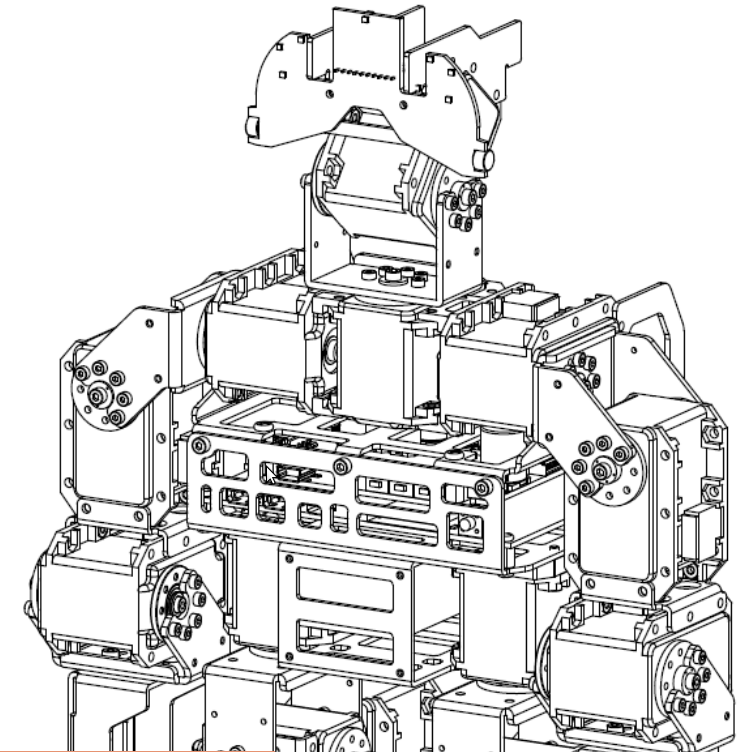
Con la primera prueba de concepto hecha, voy a continuar con las piezas del DARwIn-OP de abajo para arriba empezando con una pierna.

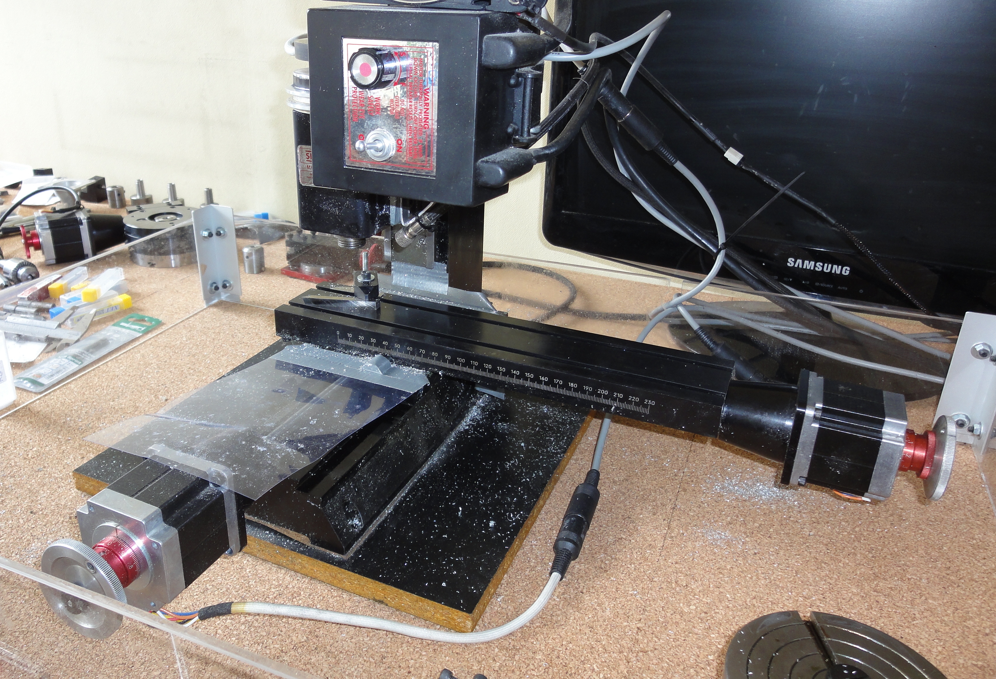
Como mi fresadora Sherline puede manejar una superficie de 200x100mm, corté las planchas de aluminio en pedazos más pequeños, después de los primeros cortes, reduje el tamaño a 150x100mm y 200×100 según las piezas a cortar.

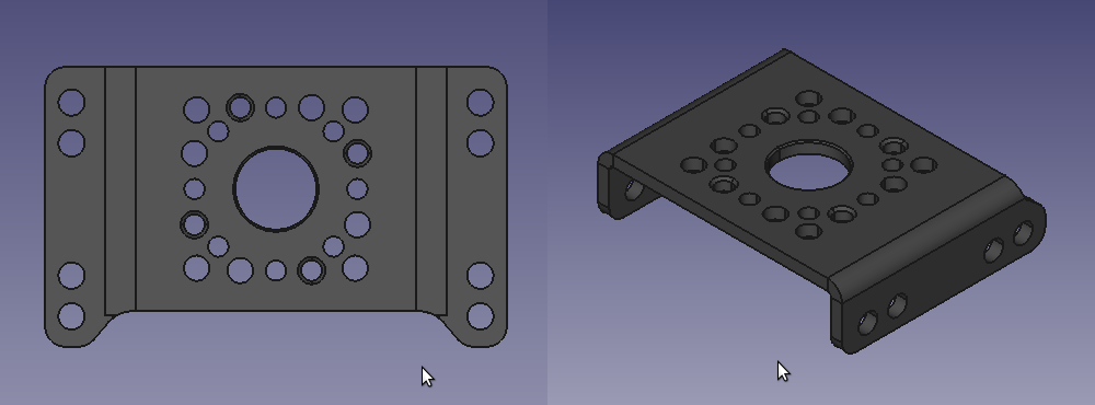
El pie es la pieza FR07_E160, el Manual de Fabricación la lista como de 1,5mm de grosor en la página 8. Pero los archivos de los modelos 2D y 3D son consistentes con una pieza de 2mm. Creo que el manual es el equivocado.

Foot and Knees

Pie y Rodillas

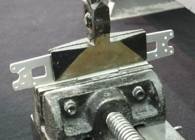
El primer pie fue cortado sobre una placa de madera de 9mm, después pasé a usar una placa de aluminio de 1/4″ como base, por la rigidez. Después entraré más en detalle en esto. Las herramientas usadas son:
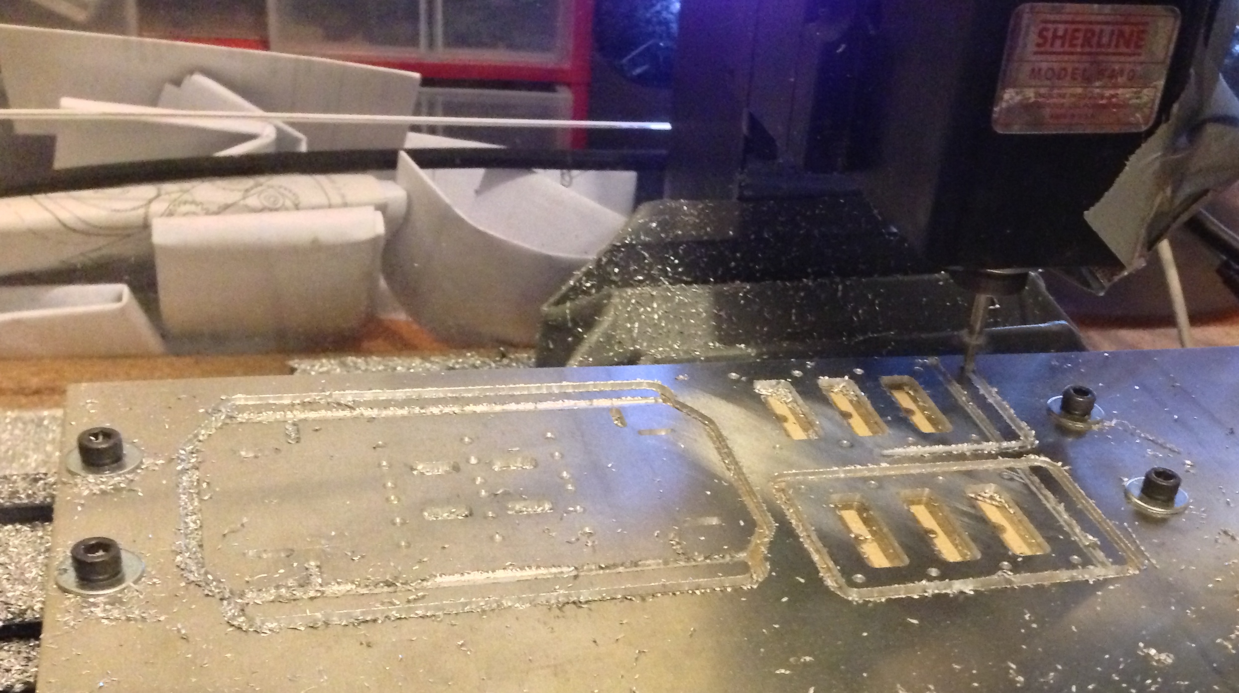
  • Broca-centro #1
  • broca de 2mm (en ese momento no tenía las brocas de 2,05mm, son agujeros para hilos de 2,5mm).
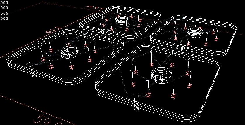
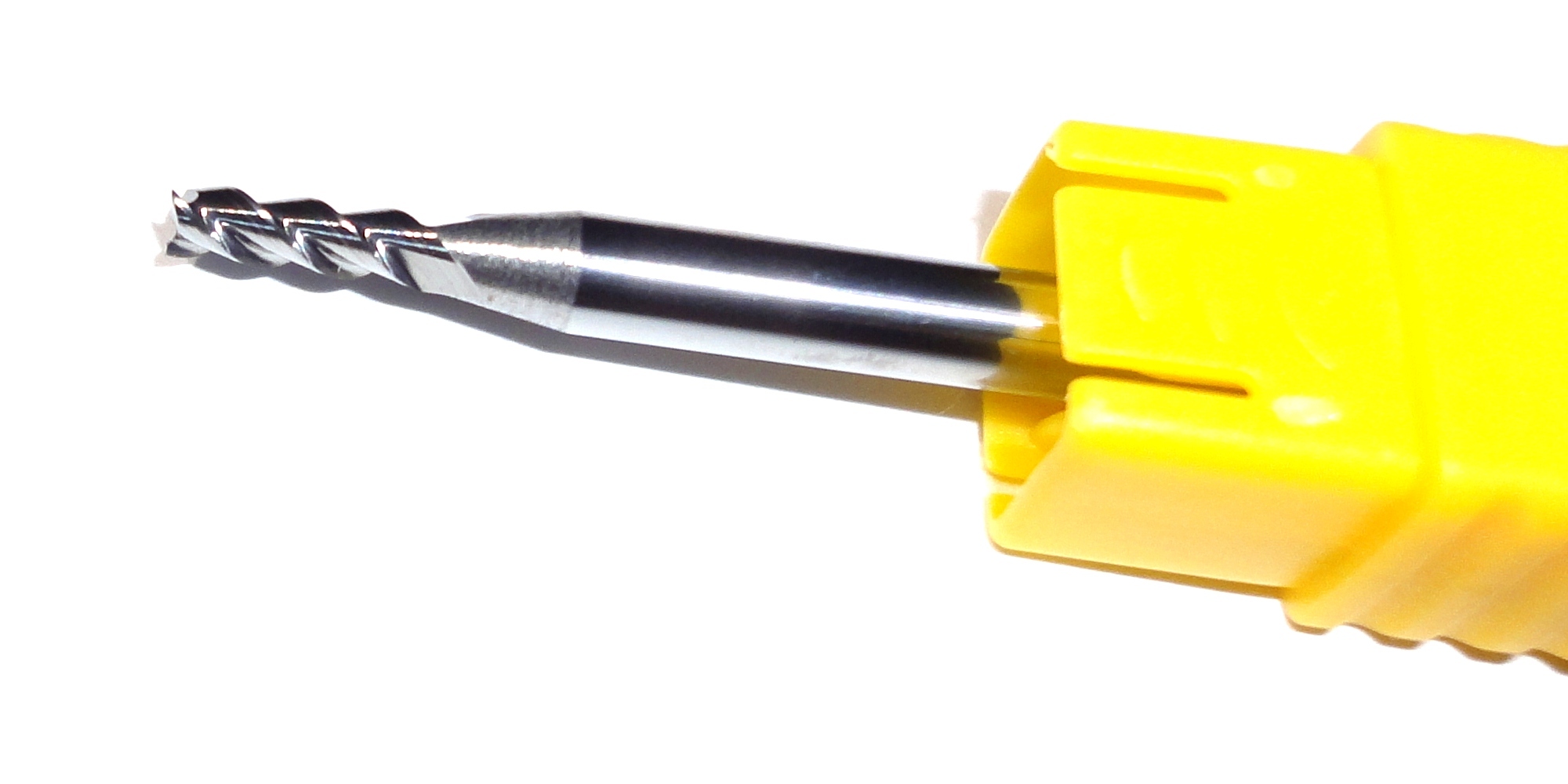
  • fresa de 2,5mm para los sacados (el sacado más delgado es de 2,6mm según el modelo
  • fresa de 3mm para cortar la pieza. Más tarde dejé de usar esta fresa ya que requiere un cambio extra de herramienta (Mi fresadora no tiene cambio automático de herramientas).

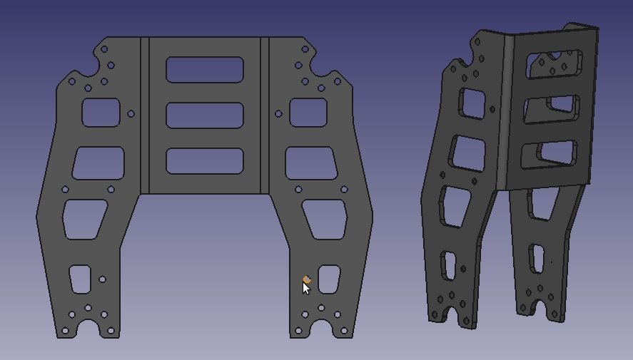
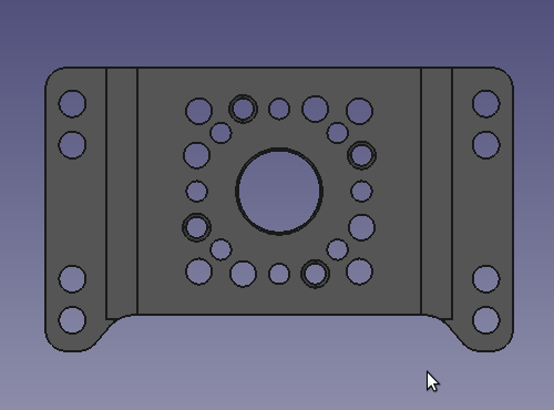
Con el pie corté un par de ‘rodillas’. El DARwIn-OP puede parecer un robot pequeño en fotografías dado que es de aprox 45cm de alto. Pero algunas de las piezas no son pequeñas, la parte bajade la pierna (FR07_H133) es aproximadamente de 118x106mm antes de doblar. Considerando además el ancho de la fresa, la fresadora se queda corta en 10mm en su eje más pequeño (Y).

Lower Leg FR07_H133
Pieza de la parte baja de la Pierna FR07_H133

Continue reading “Clonado de Primeras Piezas de DARwIn-OP”

DARwIn-OP First Frames Cloning

Now that the first proof of concept was done with the first test cut,  I am continuing with the DARwIn-OP frame parts bottom up starting with one leg.

Since my Sherline mill can manage a surface about 200x100mm. I sliced out my aluminum sheets in smaller pieces, after the first few cuts I ended up reducing the size to 150x100mm and 200x100mm pieces depending on the size of the parts to cut.

The foot is the FR07_E160 frame. The Fabrication Manual lists this part as 1.5mm thick on page 8. But the 2D and 3D model files are consistent with a 2mm thick part. I believe the manual is the one mistaken.

Foot and Knees
Foot and Knees

The first foot was cut over a 9mm wood plate. I later changed to using an 1/4″ aluminum plate as this is much more sturdy, I’ll go on this latter. The tools used are:

  • Centerdrill #1
  • drill 2mm (since at the moment I didn’t have a 2.05mm drill yet, the holes must all be 2.5mm tapped).
  • endmill 2.5mm for the slots (the thinner ones mesure 2.6mm wide on the model).
  • endmill 3mm for the cut-off. I latter stopped using the 3mm endmill as this requires an extra tool change (My mill does not a fancy automatic tool change).

With the foot I also cut a couple of ‘knees’. The DARwIn-OP may seem to be a small robot in pictures, considering it is about 45cm high (1.5 feet). But some frame parts are not as small as I imagined initially. The lower leg part FR07_H133 is about 118x106mm before bending. Considering also the endmill width,  the mill is short in about 10 millimeters in its shorter Y axis.

Lower Leg FR07_H133
Lower Leg FR07_H133

Continue reading “DARwIn-OP First Frames Cloning”

Corte de Prueba para clonar DARwIn-OP

Varias piezas del DARwIn-OP tienen un patrón recurrente donde se monta la rueda del servo. Probar bien este patrón va ayudar con el G-code de muchas piezas.

FR07-S101
Pieza FR07-S101

La pieza mostrada requiere un agujero de 8mm y 8 agujeros de 2mm alrededor en un círculo de 16mm de diámetro, cada 45°. También se ven 4 agujeros de 2,05mm un poco rotados (para hilos de 2,5mm) y 4 agujeros de 2,5mm un poco rotados en el otro sentido, éstos son para apernar 2 piezas una contra la otra. Revisando el modelo 2D de la pieza FR07-H132, éste tiene este patrón al revés, creo que es un error en el archivo 2D.

Recibí las planchas de aluminio, las fresas de 3 filos y un par de servos Dynamixel MX-28T y machos para hacer hilos de 2mm y 2,5mm. También compré un par de FR-I101 (ruedas volantes) para probar.

Dynamixel MX-28T with Horn
Dynamixel MX-28T, Rueda Motriz y Pernos

La rueda motriz del servo tiene 8 hilos de 2mm (para 8 pernos incluidos en el kit) en círculo que calzan con el patrón recurrente en los diseños. La rueda no viene instalada, lo que se hace con un perno de 2,5mm (incluido en el kit), esto debe hacerse con cuidado ya que la rueda debe alinearse con el servo, ambos tienen marcas para ello. Una vez que la rueda está puesta a medio camino se pone difícil poder sacarla.

Horn Alignment
Alineación de la rueda

Así que lo primero será hacer unos cortes de piezas de prueba para ver el tamaño adecuado para el agujero de ‘8mm’ de forma que la rueda motriz calce bien (y así no termino con piezas en las que no entre la rueda o que quede muy suelta). Para esto diseñé algunas piezas de prueba cuadradas de 24x24mm con los 8 agujeros de 2mm y el agujero central partiendo en 8mm con incrementos de 0,1mm según la pieza. El agujero central es hecho con la fresa de 3mm en movimiento circular, por lo que es importante minimizar el juego de la fresadora.

LinuxCNC view of Test Cuts
Vista de los Cortes de Prueba en LinuxCNC

Continue reading “Corte de Prueba para clonar DARwIn-OP”

DARwIn-OP Clone Test Cut

Many frame parts of the DARwIn-OP have a kind of repeating pattern where the servo horn hooks up. To get this pattern right will help on the G-code of several frames.

FR07-S101
FR07-S101

The frame requires an 8mm hole and eight 2mm holes around evenly spaced in a 16 mm diameter circle. Note also, that in the pattern there are 4 holes (2.05mm) a bit rotated that will be tapped for 2.5mm screws while there are also 4 holes (2.5mm) a bit rotated the other way around, this is used to screw 2 frames together. Looking at the FR07-H132 frame’s 2D model, it has this pattern flipped over. I think it is a mistake in the 2D file.

I got the aluminum sheets, the carbide 3 flute aluminum endmills, a couple of Dynamixel MX-28T servos with horns, and tap sets for 2mm and 2.5mm. I also bought a couple of FR07-I101 Bearing idler sets as samples.

Dynamixel MX-28T with Horn

The horn has eight taped holes for 2mm screws (included) in a circle that match the repeating design pattern. The horn does not come installed, which is done with a 2.5mm hex screw (included) and this has to be done carefully since the horn has to be aligned with the shaft on the servo. Both have marks to do this. Once the horn is most of the way plugged in, it gets quite tight and it can get really difficult to get it back out.

Horn Alignment
Horn Alignment

So the first thing should be to make some trials on how much the 8mm hole should be 8mm so the horn can fit tight (so I don’t end up with frames that don’t fit the servos or are way too loose). For this I designed a few 24x24mm test square pieces with the eight 2mm holes and a the center hole varying from 8mm up in 0.1mm increments. the center hole is done with the 3mm endmill in a circular motion, so minimizing the mill’s backlash is important.

LinuxCNC view of Test Cuts

Continue reading “DARwIn-OP Clone Test Cut”

Herramientas para Clonar el DARwIn-OP

Así que hay que fresar un montón de piezas de aluminio y tornear otras más.

Por suerte tengo una fresadora y un torno Sherline que compré hace algunos años para hacer algunas cosas entretenidas. El año pasado les terminé de instalar control CNC y ahora los manejo con LinuxCNC, que es una distribución con Ubuntu pre-instalado y configurado para uso en CNC. LinuxCNC permite ejecutar programas en G-code que básicamente describen la trayectoria que sigue la herramienta de corte.

Sherline 5410 Mill
Fresadora Sherline 5410 (métrica)
Sherline
Torno Sherline 4410 (métrico)

La fresadora y el torno Sherline están diseñados para trabajar con materiales tanto blandos como duros, hasta acero inoxidable y titanio. El aluminio no es problema, aunque estoy pensando en cambiar el motor a uno de 10.000 RPM ya que el que traen por defecto (2.800 RPM) no alcanza las velocidades de corte superficial que se recomiendan para cortar aluminio con fresas pequeñas (2.5mm y 3mm).

Es bien conveniente que el diseño del DARwIn-OP es métrico, igual que mis herramientas, así es más difícil cometer errores.

Estas herramientas son de escritorio (de hecho las tengo en un escritorio). La fresadora tiene un área de trabajo de 200×100 mm aprox, lo que es muy pequeño para clonar algunas piezas del DARwIn-OP como las manos o la parte baja de la pierna, así que voy a tener que rediseñarlas en partes que se unan con pernos. Una fresadora más grande o un router CNC habrían sido ideales para cortar varias piezas de una sola vez, pero con la que tengo se puede hacer el trabajo.

Para la fresadora, las herramientas de corte que usaré son:

  • Fresas de 2,5mm y 3mm. Voy a comprar unas fresas para aluminio de carburo de 2 y 3 filos para probarlas.
Endmill for aluminum
Fresa para aluminio

Continue reading “Herramientas para Clonar el DARwIn-OP”

DARwIn-OP Clone Manifacturing Tools

So I have to mill a bunch of aluminum frame parts and a few more have to be made on a lathe.

By chance, it happens that I own a Sherline mill and a lathe which I bought many years ago just to do some ‘cool’ stuff. Last year I finished installing CNC control on both and now I run them with LinuxCNC which is an Ubuntu distribution preinstalled and configured for CNC usage. LinuxCNC runs G-code programs which basically describe the path that the cutter will follow.

Sherline 5410 Mill
Sherline 5410 Mill (metric version)
Sherline Lathe
Sherline 4410 Lathe (metric version)

The Sherline mill and lathe are designed to work with soft or hard materials like stainless steel an titanium. Aluminum is no problem, though I may upgrade the pulley to the 10,000 RPM model since aluminum requires higher surface cutting speed than what you can get with the stock 2,800 RPM pulley when you are using small endmills (2.5 mm and 3 mm).

A nice thing is that the DARwIn-OP design is metric, as does my tools, so it is harder to screw up.

These tools are desktop size (I actually have them in a desktop). The mill has a working area about 200×100 mm which is too small for some of the frame parts to clone a DARwIn-OP such as the hand or the lower leg. So these parts I’ll have to redesign in several pieces that can be screwed together. A much bigger mill or a CNC-router would have been ideal for cutting a lot of pieces at once, but the tools I have can do the job.

For the mill, the cutters I’ll use are:

  • 2.5mm and 3mm endmills. I’ll get some 2 flutes and 3 flutes carbide endmills for aluminum and check them out.
Endmill for aluminum

Continue reading “DARwIn-OP Clone Manifacturing Tools”

Diseños Mecánicos y Manuales de DARwIn-OP

El robot DARwIn-OP tiene varios documentos mecánicos publicados en esta carpeta de sourceforge. Los documentos están bien hechos y bastante completos, fueron escritos por RoMeLa de Virginia Tech.

DARwIn OP Fabrication Manual.pdf

  • Describe cómo fabricar las piezas necesarias para clonar el DARwIn-OP. Literalmente el robot es un montón de servos unidos por piezas de aluminio.
Armazón de DARwIn-OP
  • Recomienda usar aluminio 5025 para fabricar las piezas. Acá en Chile no es fácil de encontrar, así que compré un poco en Ebay. Ahora sé que éste es aluminio naval y que es usado para embarcaciones, así que hay más dónde preguntar. No recomiendo usar aluminio 1100 (el típico en plancha) porque se pega a las brocas y fresas mucho.
  • Lista los archivos de diseño para cada pieza.
  • Lista las herramientas a usar y explica el proceso de fabricación, el cual requiere una fresadora automatizada (CNC). Las piezas se hacen principalmente de planchas de aluminio de 2mm y 1,5mm y se explican varias técnicas de doblado par darles la forma 3D (dependiendo de las herramientas que se tengan a mano). Algunas piezas requieren planchas de 5mm (o 1/4″). También se necesitan hacer hilos de 2mm y 2,5mm.
Doblado de Pieza
Doblado de Pieza
  • También lista un estimado de costos (USD) de materiales y herramientas.
  • Este ZIP contiene los diseños 2D y 3D de las piezas, todas disponibles en 3 formatos diferentes(STEP, PRT, IGS). Los diseños 2D son en realidad diseños 3D de las piezas sin doblar y los diseños 3D son de la forma final de las piezas después del doblado. Yo uso FreeCAD para Ubuntu (disponible por apt-get) para visualizar y medir archivos STEP.
Diseño 2D y 3D de Pieza FR07_S101

Continue reading “Diseños Mecánicos y Manuales de DARwIn-OP”

DARwIn-OP Mechanical Designs and Manuals

The DARwIn-OP has several mechanical documents published in this sourceforge directory. The documents are well done and fairly complete. They were written by RoMeLa at Virginia Tech.

DARwIn OP Fabrication Manual.pdf

  • It describes how to manufacture the frames needed to clone a DARwIn-OP. Literally the robot is a lot of servos stitched together by aluminum parts (the frames).
DARwIn-OP Frame
DARwIn-OP Frame
  • It  recommends aluminum 5025 to make the parts. Where I live (Chile) this is not easy to find so I bought some sheets on Ebay from a US seller. Now I know this aluminum is used for naval ships so I still may have a chance here. I do not recommend using pure aluminum 1100 (which is common for sheets at least here) as it sticks on drills and endmills too much.
  • It lists which design files go for each part.
  • It lists the tools to be used and explains the manufacturing process which requires a CNC mill. The frame parts are made mostly with 2mm and 1.5mm aluminum sheets. Several bending techniques are explained to shape them 3D (depending on the tools you have). Some other parts require 5mm (or 1/4″) sheets. Also 2mm and 2.5mm tapping is required.
Frame Bending
Frame Bending
  • It also estimates (US prices) the cost in tools and materials.
  • This ZIP contains 2D and 3D designs for the frame parts, all available in 3 different formats (STEP, PRT, IGS). The ‘2D’ files are actually 3D models of the unbend parts. The ‘3D’ files are 3D models of the finished parts after bending. I use FreeCAD on Ubuntu (available by apt-get) to visualize and measure the parts in STEP format.
Frame FR07_S101 2D and 3D models

Continue reading “DARwIn-OP Mechanical Designs and Manuals”