
I bought both a Sherline mill and a lathe a few years ago.
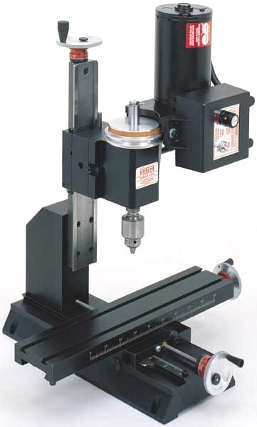
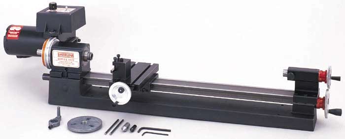
Right away I decided to add computer numerical control (CNC) by buying the hardware (stepper motors and mounts from Sherline) and save money by customizing the electronics.
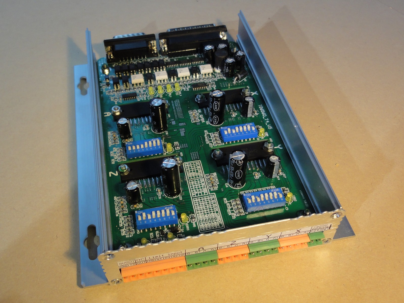
There are some nice 3 and 4 axis stepper motor controllers available with the Toshiba TB6560AHQ chip, which is a PWM driver with microstepping capabilities and up to 3.5A capacity per phase. These controllers can be connected to a PC through a parallel port (which is preferred because of low latency) and cost less than 100 USD.
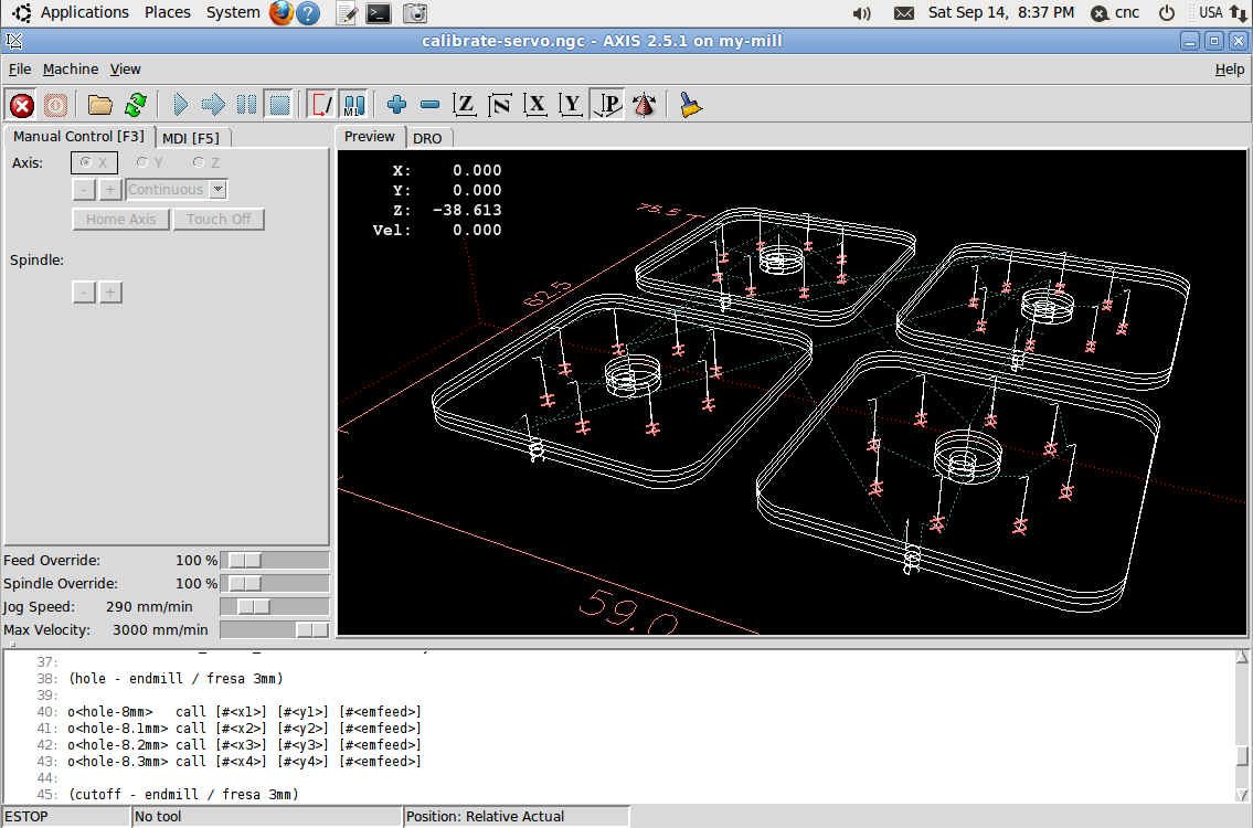
On a PC, LinuxCNC is an Ubuntu based Linux distribution (with an ISO installer) with real time extensions (needed to run the stepper motors smoothly) and CNC software to run G-code programs. It can be easily setup to use a parallel port stepper controller.
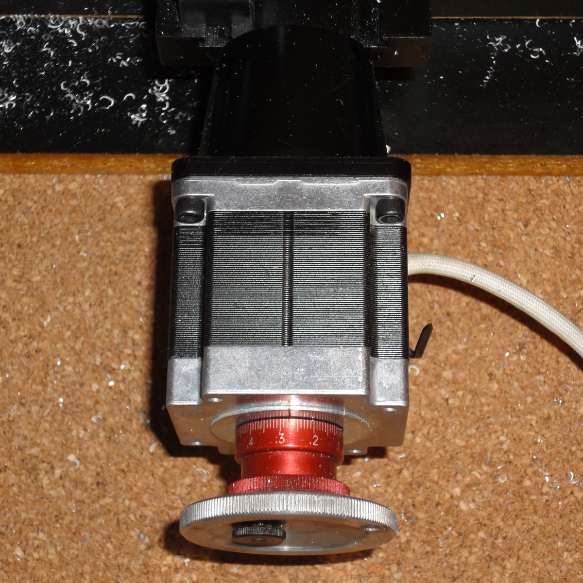
The original Sherline stepper motor is rated 2A and 3.2V. Most stepper motor controllers based on the Toshiba TB6560AHQ chip available in places like ebay are rated 3.5A but can be setup to 70%, 50% or 20%. So a 50% setup would give a would give me a 1.75A current level, which is close enough to the motor rating. Also a 24V and 8A power supply is enough to power the controller, a much higher voltage than the motor’s rating is needed to step it fast by forcing a current change in the motor’s coils at high voltage.
Anyway, by checking the Toshiba TB6560AHQ datasheet, I noticed that the maximum current level is defined by a couple of resistance (R) connected to pins 11 and 14 (one for each motor phase). The maximum current is set to 0.5V/R. These resistances have to withstand the maximum current at 0.5V, that means 1.75W for a 3.5A setup. They should be big enough for this power rating. By looking at my 4 axis controller circuit board, no big resistance are visible. So I disassemble the board (which has each driver screwed for power dissipation) and I looked on the lower side, finding 2 sets of 3 big resistances per driver.
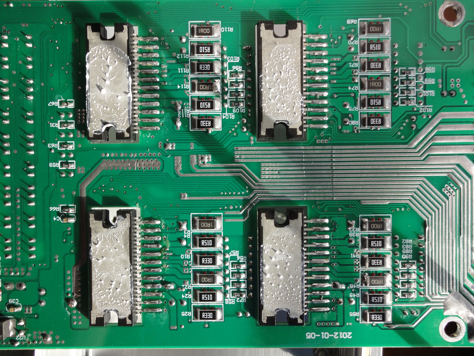
These resistances seem to be in a parallel configuration and have values of 1Ω, 0.51Ω, and 0.33Ω. The equivalent resistance is then 0.167Ω, which means a 3A max current (my controller was documented to be rated 3.5A which seems not to be the case). The 50% configuration that I was considering would give me a 1.5A setup, much lower than the 2A motor rating.
Now, if the controller had only the 1Ω and the 0.33Ω resistances, that would be equivalent to 0.248Ω, which means a 2.02A max current, close enough to the motor rating. So I only have to remove the 0.51 Ω resistances and set the controller to 100%.
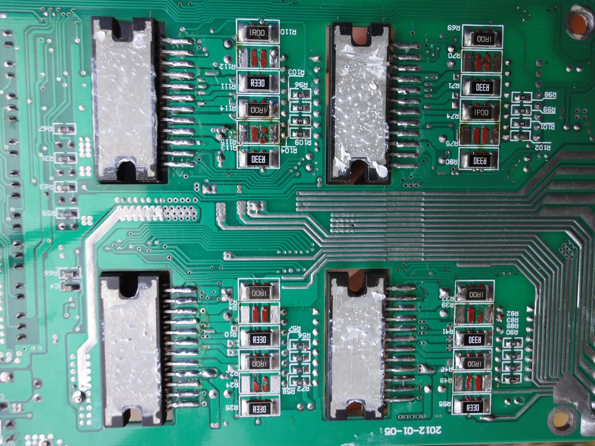
Somebody did a good design with these 3 resistances in parallel, you can setup a maximum current of 0.5A, 1A, 1.5A, 2A, or 2.5A by removing 1 or 2 resistances.