The DARwIn-OP has several mechanical documents published in this sourceforge directory. The documents are well done and fairly complete. They were written by RoMeLa at Virginia Tech.
DARwIn OP Fabrication Manual.pdf
- It describes how to manufacture the frames needed to clone a DARwIn-OP. Literally the robot is a lot of servos stitched together by aluminum parts (the frames).
- It recommends aluminum 5025 to make the parts. Where I live (Chile) this is not easy to find so I bought some sheets on Ebay from a US seller. Now I know this aluminum is used for naval ships so I still may have a chance here. I do not recommend using pure aluminum 1100 (which is common for sheets at least here) as it sticks on drills and endmills too much.
- It lists which design files go for each part.
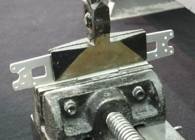
- It lists the tools to be used and explains the manufacturing process which requires a CNC mill. The frame parts are made mostly with 2mm and 1.5mm aluminum sheets. Several bending techniques are explained to shape them 3D (depending on the tools you have). Some other parts require 5mm (or 1/4″) sheets. Also 2mm and 2.5mm tapping is required.
- It also estimates (US prices) the cost in tools and materials.
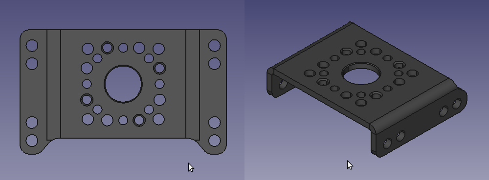
- This ZIP contains 2D and 3D designs for the frame parts, all available in 3 different formats (STEP, PRT, IGS). The ‘2D’ files are actually 3D models of the unbend parts. The ‘3D’ files are 3D models of the finished parts after bending. I use FreeCAD on Ubuntu (available by apt-get) to visualize and measure the parts in STEP format.
- It containts the 3D model files (in STEP format) of the plastic cover parts.
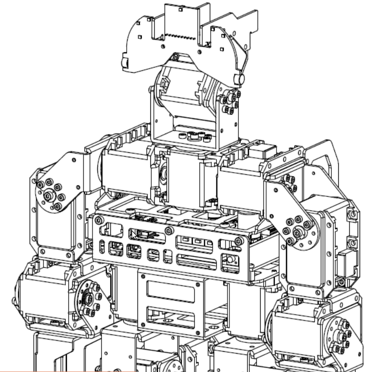
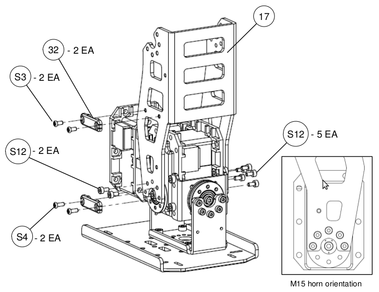
- It describes the process of assembly of the servos, frames, and motherboard. The assembly is done in parts like legs, lower chest, upper chest. At the end these parts are put together. Note that the servos have a powered horn in one side and may require an unpowered idler at the other side for structural integrity, it is crucial to install the servos with the horn to the specified side and with the horn marks oriented as required since the MX-28T servo has absolute encoding of its position (the Control Software expects a certain value for the up standing position for example).
- It lists all parts required including nuts, screws, bearings.
- It contains a list of files with the dynamics specification of the robot (mass, center of mass and inertia specs) for each part. These are not needed for the fabrication of the DARwIn-OP clone but it is worth to mention since these files are useful for simulation and control purposes. Building the clone to spec with the original materials and fabrication process helps in keeping the robot close to these dynamics specs so when walking it doesn’t tip over because some leg or arm is too heavy or light (though I do want to implement a parameter identification algorithm in the future so the robot can maintain and update its dynamics specs as time goes by).
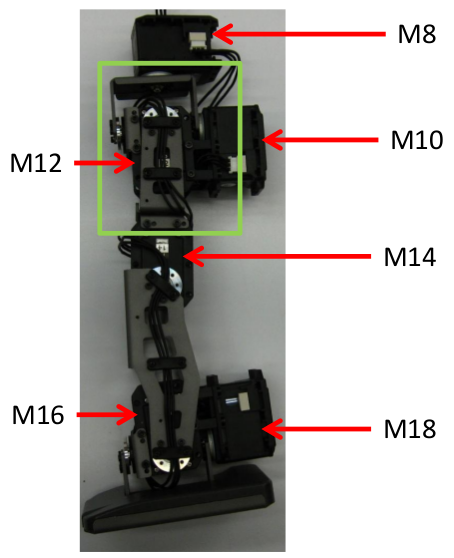
- It enumerates the MX-28T servos and shows how to wire them and the rest of the electronics. These servos are connected in a daisy-chained fashion in a power and serial data bus (TTL 3 wire bus). Before a servo can be daisy-chained it has to be programmed with the proper ID as shown in the manual because these servos come preset from factory with ID = 1 and two servos with the same ID with result in data collisions in the bus. I don’t quite like the wiring with those plastic cable holders, I’ll try to find another way to avoid it, but I’ll probably have to go with this cable holder design since it holds the cable tight and bends it properly at the joint axes.
The documentation is quite comprehensive and there are a few more design documents in this sourceforge directory, I just mentioned the most important information.
There are some designs missing, mostly for circular parts which should be made in a lathe and not in a mill:
- Servo horn (HN07-N101). These I’ll buy since they have a serrated shaft that assembles with the servo and that requires more specialized tools. If you buy a single servo it will come with the horn but the 6-pcs bulk package does not and they have to be bought separately.
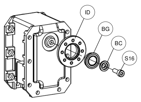
- Bearing idler (HN07-i101).
- Flange bearing (FR07-F101).
- Bearing cap (RX28 CAP BEARING).
- Cable holder (seems to be plastic).
For some of these, except the for cable holder, I found the design files in this Robotis Support web page. Also, several other parts have design files in several formats on that page.
After thinking for a while about it, I decided that I’ll make the Bearing idlers, Flange bearings, and Bearing cap with a lathe (they are also available in several robotics online store, I purchased a couple for testing), the idler also requires 8 holes to by made in a mill. The ball bearing that goes between the idler and the cap is a MF106ZZ model bearing (6x10x3mm) which is available at Ebay at about 1 USD.