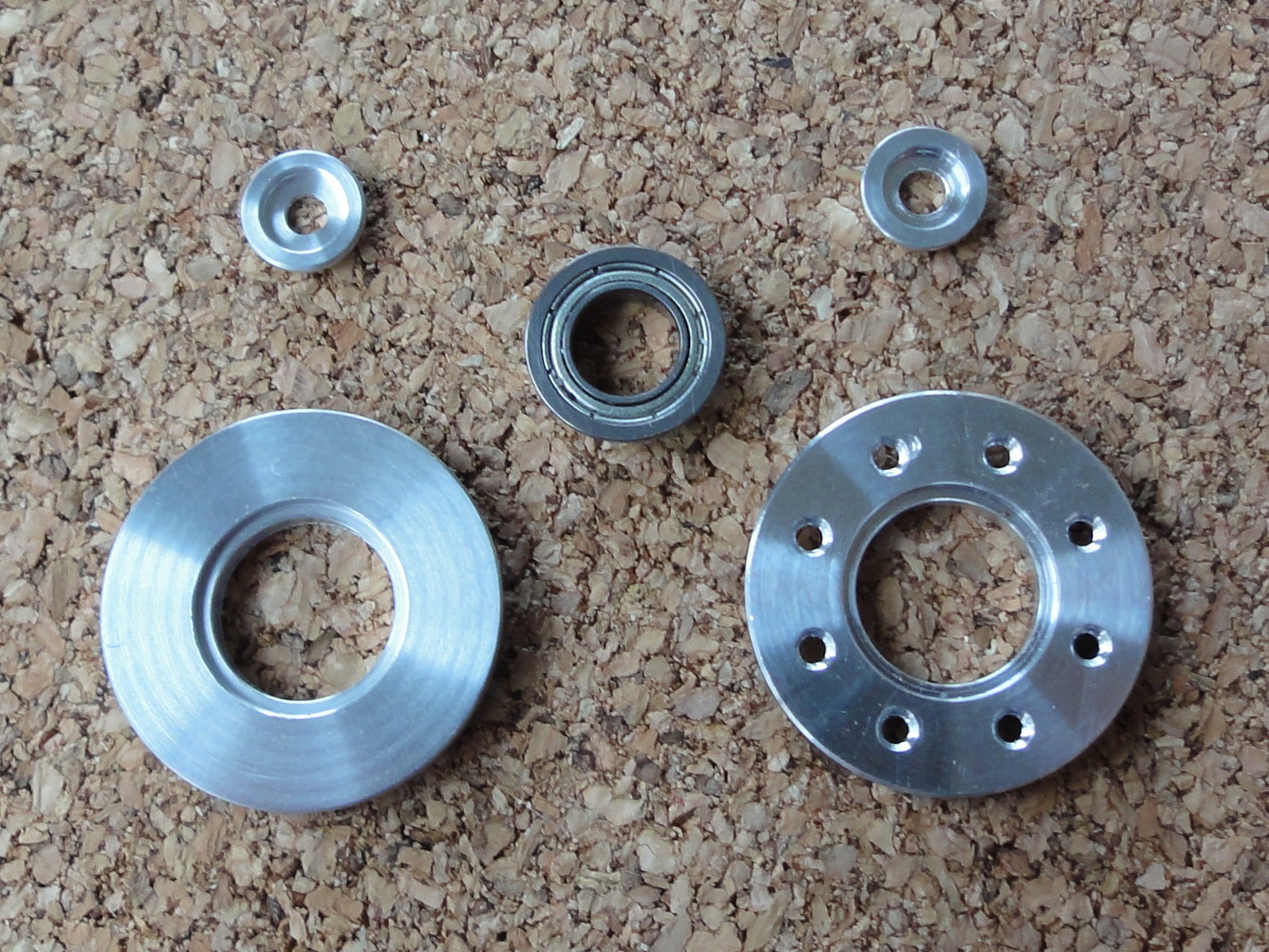
HN07-I101 y RX28-CAP (cortes de prueba a la izquierda y original a la derecha)
Logré cortar el HN07-I101 y el RX28-CAP. Tengo un set original que compré por lo que puedo compararlos, el rodamiento calza lo suficientemente justo. Todavía tengo que hacer los agujeros, pero haré algunas herramientas para hacerlos en la fresadora. Además tengo que pulirlos y anodizarlos.
Usé unos restos de aluminio 20XX que tenía, una barra de 1″ para el HN07-I101 y una barra de 5/8″ para el CAP, todavía estoy esperando unas barras de 15/16″ y 3-8″ de aluminio 6061 para hacer las piezas finales. El código G-code de corte está en la Sección de código de mi proyecto sourceforge, requieren una configuración de cambio rápido (o automática) con este setup de herramientas.
HN07-I101 and RX28-CAP (my cuts on left and original on right)
I manage to cut the HN07-I101 and RX28-CAP. I have an original set that I bought, so I am able to compare, the ball-bearing fits tight enough. I still have to make the holes, but I’ll device some tools to use on the mill for this. Then I still have to polish and anodize.
I used some spare 20XX aluminum that I had, a 1″ bar for the HN07-I101 and a 5/8″ bar for the CAP, I am still waiting for some 6061 aluminum 15/16″ and 3/8″ bars to do the final pieces. The G-code cut programs are available on the Code section of my sourceforge project, they require a quick (or automated) change tool post with this setup of tools.
Para continuar con mi Clon del Robot DARwIn-OP,necesito hacer algunas piezas en mi torno Sherline.
Para esto, lo más práctico es una configuración de cambio rápido.
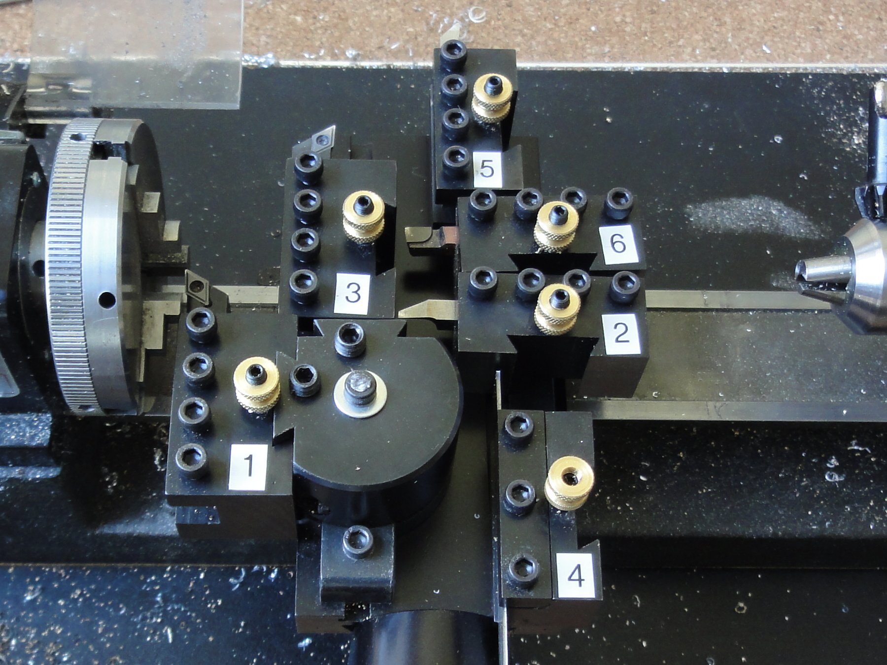
Herramientas de Cambio Rápido (actualizado)
El usar herramientas de cambio rápido permite calibrarlas una sola vez y luego, al cortar piezas, poder intercambiarlas en unos pocos segundos, volviendo a sus posiciones iniciales con un mínimo margen de error.
Las herramientas base que ocuparé son:
Cuchilla de Corte Derecha (incrustación de 55)
Cuchilla para mandrinado (para agujeros)
Cuchilla de Corte Izquierda (incrustación de 55° para corte posterior)
Cuchilla de Tronzado (para la separación final de la pieza)
Cuchilla de Corte Izquierda (con punta de mínimo radio para esquinas)
Cuchilla de Corte Izquierda (en posición para cara derecha)
Cuchilla de Tronzado Derecho (la misma herramienta #4, calidrada para corte derecho)
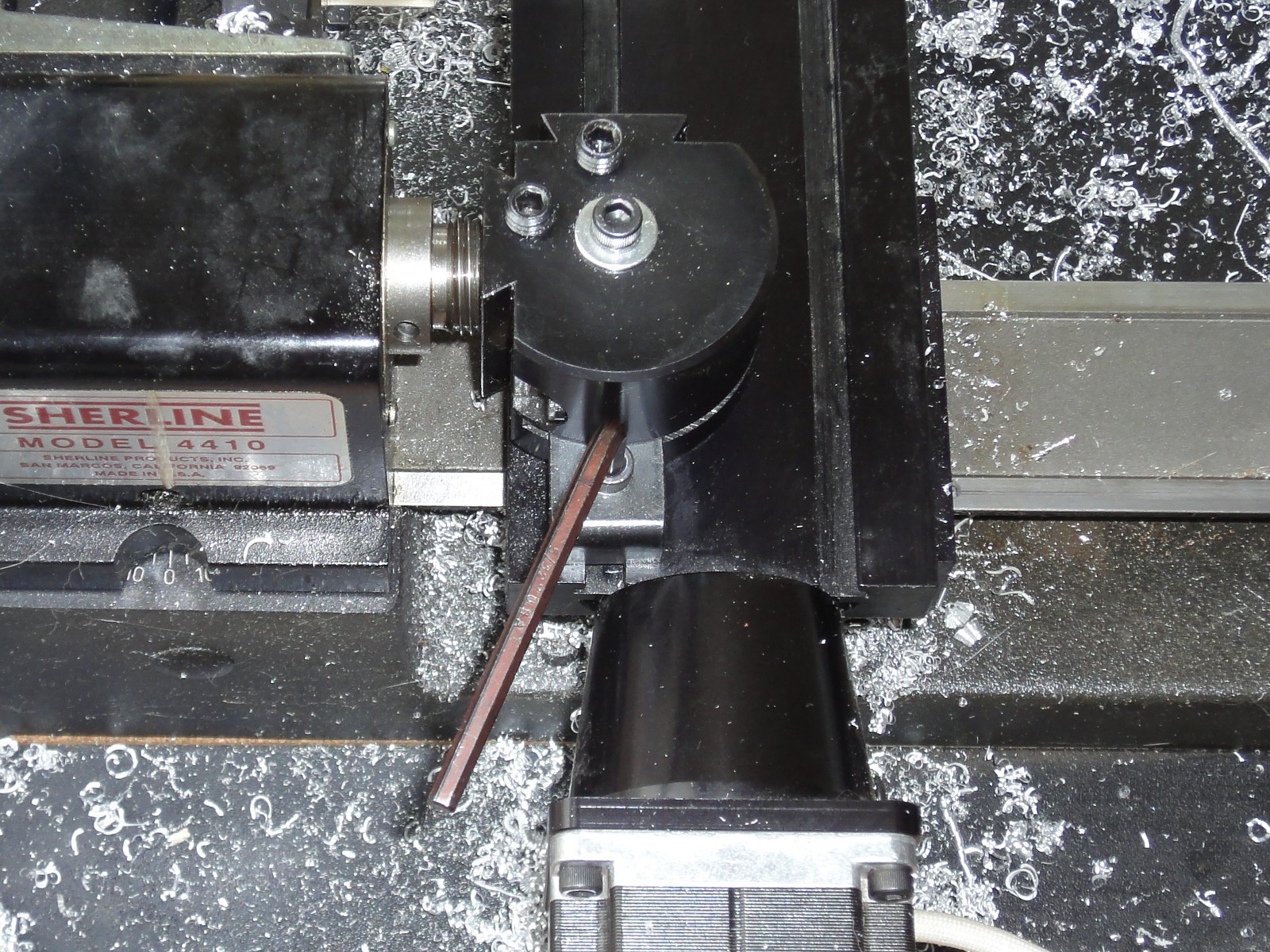
La torre de cambio rápido debe alinearse especialmente para la cuchilla de tronzado, yo uso el cabezal para hacer el alineamiento.
Alineamiento de la Torre de Cambio Rápido
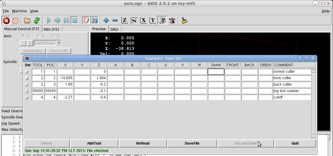
Para la operación CNC, las herramientas deben ser configuradas en la tabla de herramientas de LinuxCNC de forma que el software compense las distintas posiciones de cada una.
Tabla de Configuración de Herramientas
Varias pruebas de cortes son necesarias para calibrar los offsets X e Y de cada herramienta, también se puede configurar la curvatura de la punta de corte.
El uso de un torno CNC debe hacerse con cuidado. Un mal movimiento puede golpear una cuchilla contra la barra de metal mientras que el software CNC ni se entera, además la torre de cambio rápido se desalineará y las calibraciones tienen que hacerse nuevamente. También es bueno seguir algunas pautas de seguridad como apagar el torno antes de manipular cuchillas o brocas.
So, to continue with my DARwIn-OP Robot Clone, I need to make a few parts on the Sherline lathe.
For this, a quick change setup is really practical.
Quick Change Tools Setup (updated)
Using quick change tools allows to calibrate each tool once. Later, when cutting parts, the tools can be easily swapped in a few seconds, settling back again to the same positions with minimal margin of error.
The basic tools I use are (updated):
Right Hand Cutter (55° insert)
Boring Cutter (for hole boring)
Left Hand Cutter (55° insert for back face cutting)
Cutoff Cutter (for cutting off the part from the stock metal)
Left Hand Cutter (minimum radius tip for corners)
Left Hand Cutter (in position for right facing)
Right Hand Cutoff Cutter (tool #4 but calibrated for right and cutting)
The quick change tool post must be aligned specially for the cutoff cutter to be aligned when cutting. I use the headstock to do the alignment.
Quick Tool Post Alignment
For CNC operation, the tools have to be configured in LinuxCNC’s tool table. So the software can compensate for the offsets for each tool.
Tool Table Configuration
Several test cuts have to be made to properly calibrate the tools X and Z offset, also the tool nose diameter can be setup to compensate on diagonal cuts.
Anyway, using a lathe (and a CNC version) have to be done cautiously. A wrong move could hit a cutter or its holder with the metal block you intend to cut and the CNC software won’t notice, plus the quick change tool post will get misaligned and all the calibration will have to be done again. It is also good to follow some safety guidelines like always turning off the lathe before switching tools or drills.
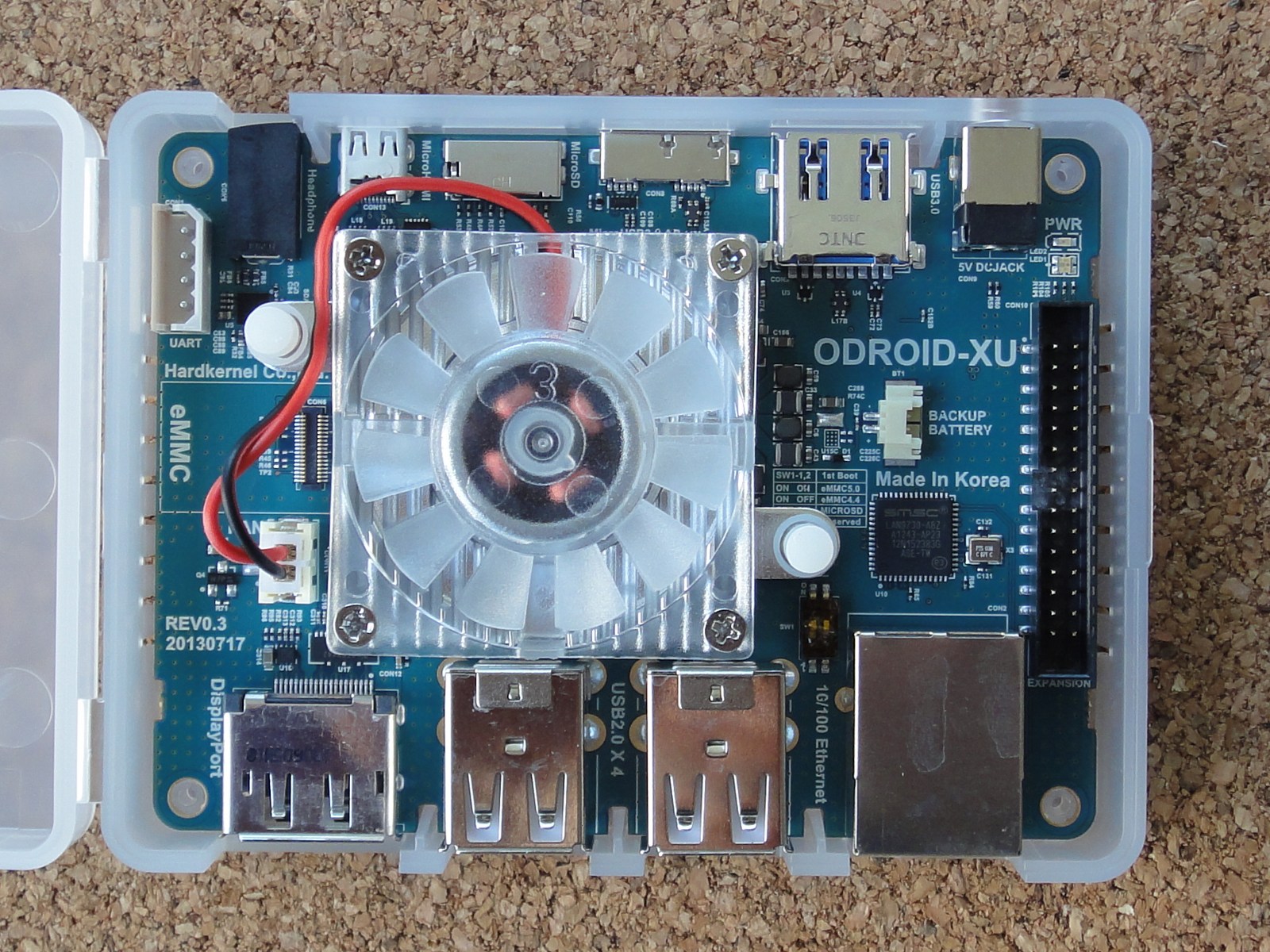
Hoy recibí mi placa ODROID-XU (ARM Cortex-A15). Mientras escribía el post Prueba de Pierna Clon de DARwIn-OP me fijé que HardKernel estaba haciendo una preventa de la placa. Compré una y me llegó muy rápido!
ODROID-XU
Las specificaciones son:
– Arquitectura ARM big.LITTLE.
– Exynos 5410 Octa, con 4 CPUs Cortex-A15 1.6GHz y 4 CPUs Cortex-A7 1.2GHz.
– 2GB de RAM.
– Ethernet de 100Mbps.
– Corre Android o Ubuntu.
– Puede usar SD o un módulo eMMC (8 a 64GB) como disco duro.
– 2 puertos USB 3.0 y 4 puertos USB 2.0.
– tamaño de placa: 94x70mm.
La placa es muy pequeña y de bajo perfil, debería ser una buena elección para mi clon del robot DARwIn-OP. El módulo eMMC viene con Android preinstalado, así que voy a instalar Ubuntu y hacer unas pruebas.
Today I got my ODROID-XU (ARM Cortex-A15) board. While writing my DARwIn-OP Clone Leg Test post I noticed that HardKernel was doing a presale of the board. I ordered one and got it fast!
ODROID-XU
The specifications are:
– ARM big.LITTLE architecture.
– Exynos 5410 Octa, with Quad Cortex-A15 1.6GHz CPUs and Quad Cortex-A7 1.2GHz CPUs.
– 2GB RAM.
– USB 2.0 and 100Mbps Ethernet.
– Runs Android or Ubuntu.
– Can use an SD or a eMMC module (8 to 64GB) as hard drive.
– 2 USB 3.0 and 4 USB 2.0 ports.
– 94x70mm board.
The board is very small and low profile. It should be an excellent choice to put on my DARwIn-OP robot clone. The eMMC module comes with Android preinstall, so I’ll be installing Ubuntu and doing some tests.
Empecé a subir los archivos de gcode para la primera pieza (fr07_s101).
Los archivos están en la sección de Código en un repositorio Subversion. Bajo la carpta mill están los archivos gcode y el archivo de texto 00_README.TXT explicando el uso. Seguiré subiendo a medida que revise y limpie los archivos del resto de las piezas.
I started to load gcode files for milling the first frame, the fr07_s101.
The files are at the Code section in a Subversion repository. Under the mill folder are the gcode files and the 00_README.TXT text file explaining the usage. I’ll be uploading more frames as I clean and check the files.
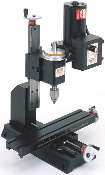
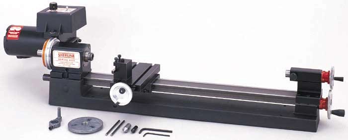
Compré un torno y una fresadora Sherline unos años atrás.
Fresadora SherlineTorno Sherline
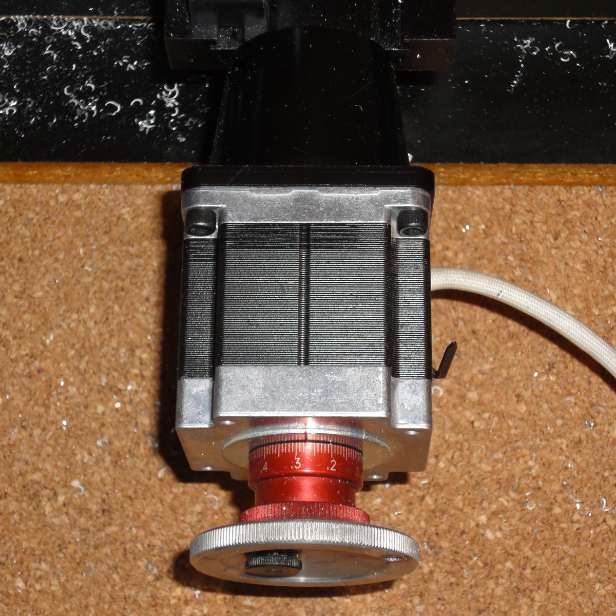
Rápidamente decidí agregarle control numérico por computadora (CNC) y terminé comprando el hardware (motores de paso y los acoples de Sherline) y ahorrando un poco customizando la electrónica.
Motor de Paso y Acople
Hay disponible controladores de paso de 3 o 4 ejes basados en el chip Toshiba TB6560AHQ que es un driver PWM con microstepping y capacidad de hasta 3.5A por fase. Estos controladores se conectan a un PC vía puerto paralelo (que es preferido por la baja latencia) y cuestan menos de 100 USD.
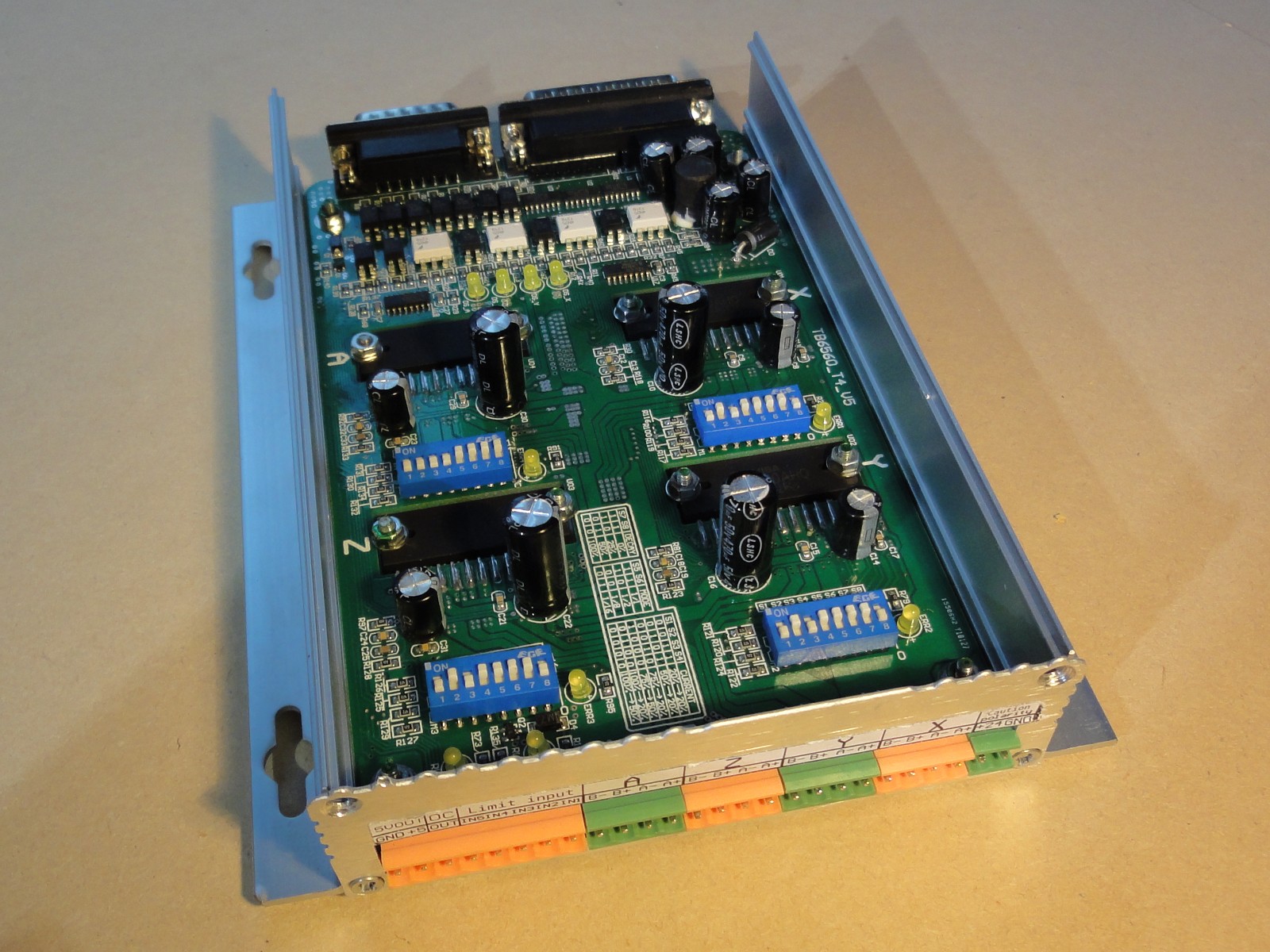
Controlador de Paso de 4 ejes
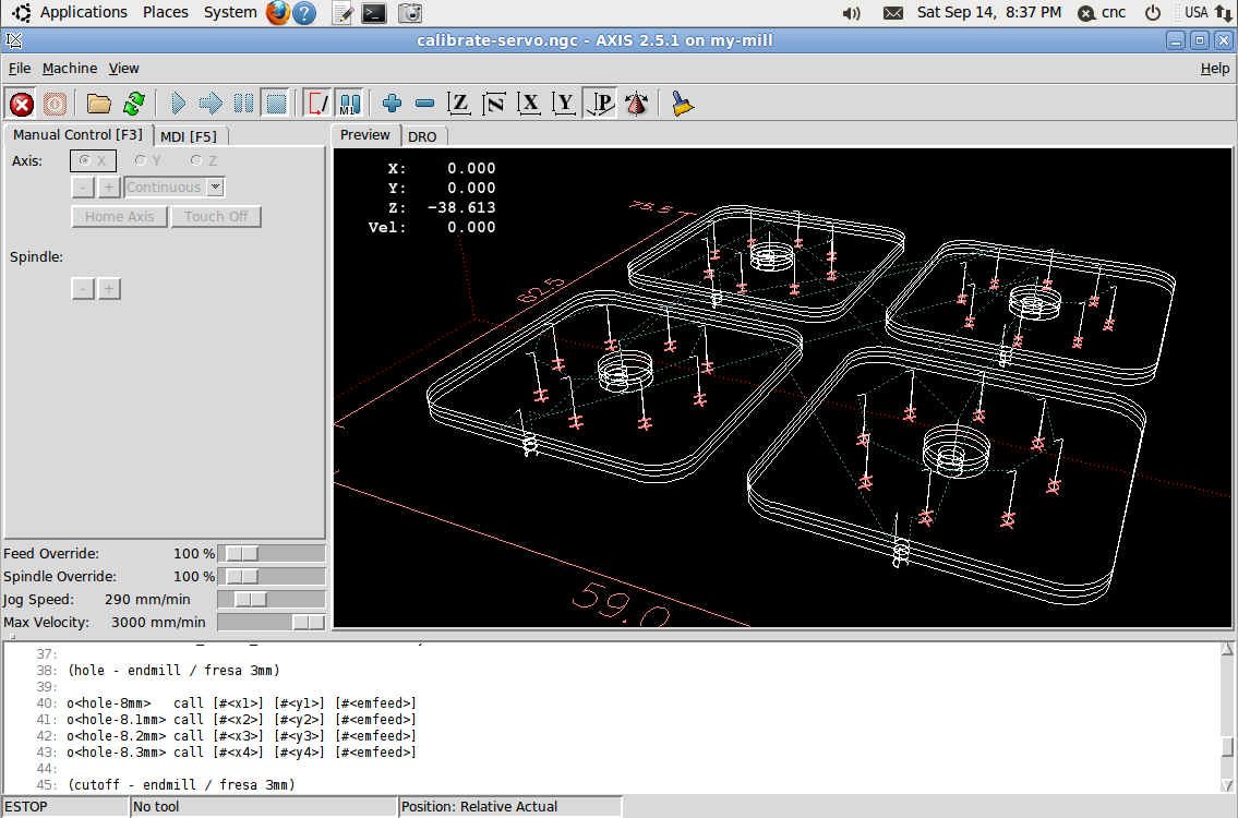
Para PC, LinuxCNC es una distribución de Linux basada en Ubuntu (con instalador ISO) con extensiones de tiempo real (necesarias para girar los motores en forma pareja) y software CNC para ejecutar programas G-code y puede configurarse fácilmente para usar controladores por puerto paralelo.
LinuxCNC
El motor de paso original de Sherline es de 2A y 3.2V. La mayoría de las controladoras basadas en el Toshiba TB6560AHQ disponibles en lugares como ebay son de 3.5A, pero se pueden configurar al 70%, 50% or 20%. Así, a 50% me daría una corriente de 1.75A que es bastante cercana a la especificación del motor. También, una fuente de poder de 24V y 8A es suficiente para energizar el controlador, se necesita un voltaje mucho más alto que el especificado por el motor para darle un paso rápido ya que se debe forzar un cambio rápido de corriente en las bobinas del motor a un alto voltaje transiente.
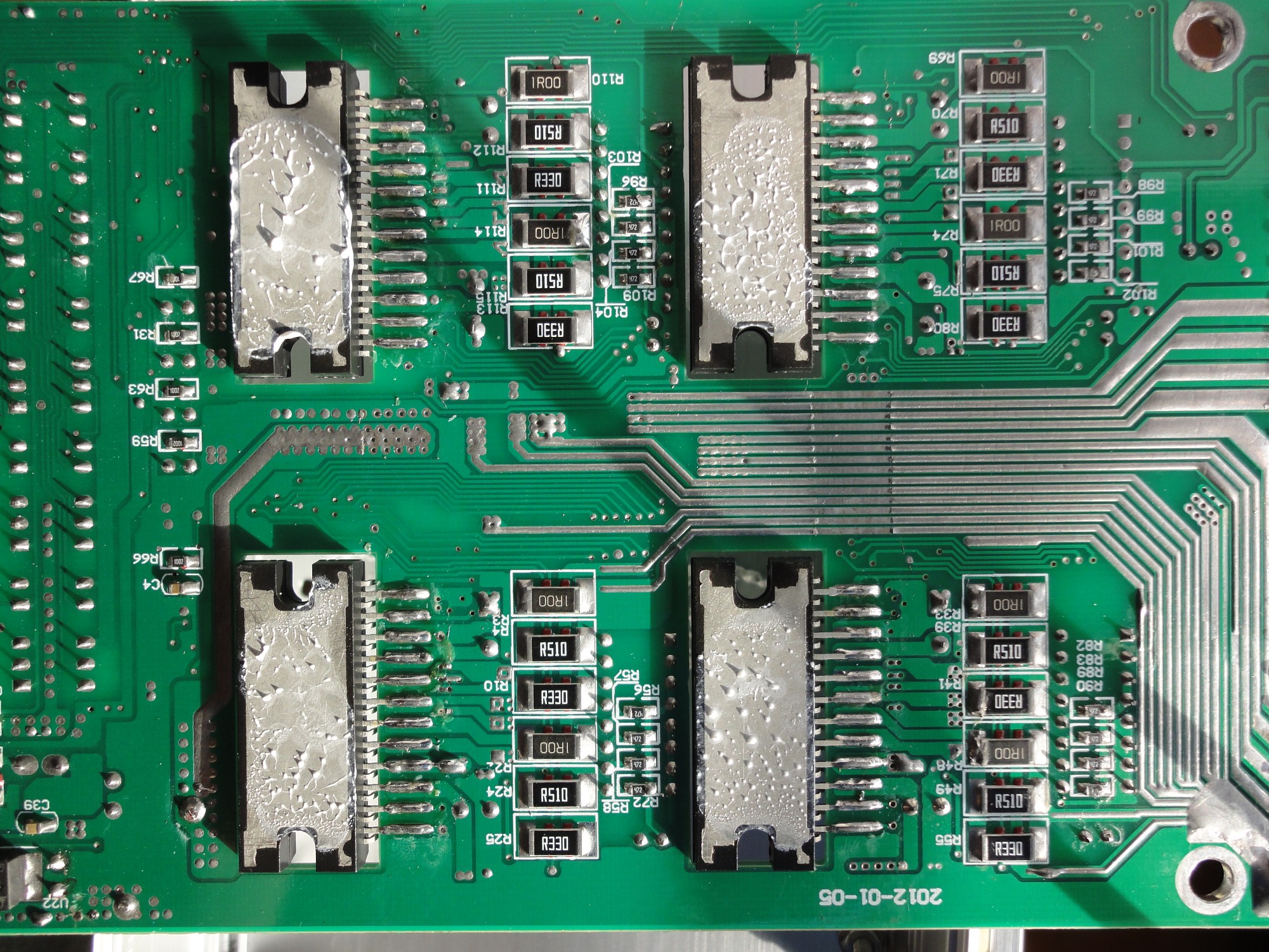
Por otro lado, revisando los manuales del chip Toshiba TB6560AHQ, noté que el nivel máximo de corriente se configura con un par de resistencias (R) conectadas a los pines 11 y 14 (uno por cada fase). La corriente máxima es 0,5V/R. Estas resistencias tienen que soportar la corriente máxima a 0.5V, lo que significa 1.75W para 3.5A y deberían ser bastante grandes. Mirando la placa del controlador, no hay resistencias grandes visibles, así que desensamblé la placa (cada driver está apernado) y por el lado inferior se ven 2 grupos de 3 resistencias por driver.
Resistencias de control de corriente en controlador de paso
Estas resistencias parecen estar en paralelo y tienen valores de 1Ω, 0,51Ω y 0,33Ω. La resistencia equivalente es de 0,167Ω, lo que implica una corriente máxima de 3A (y se suponía que mi controlador era de 3.5A según la documentación). La configuración al 50% que estaba considerando me daría 1.5A, bastante menos que los 2A de la especificación del motor.
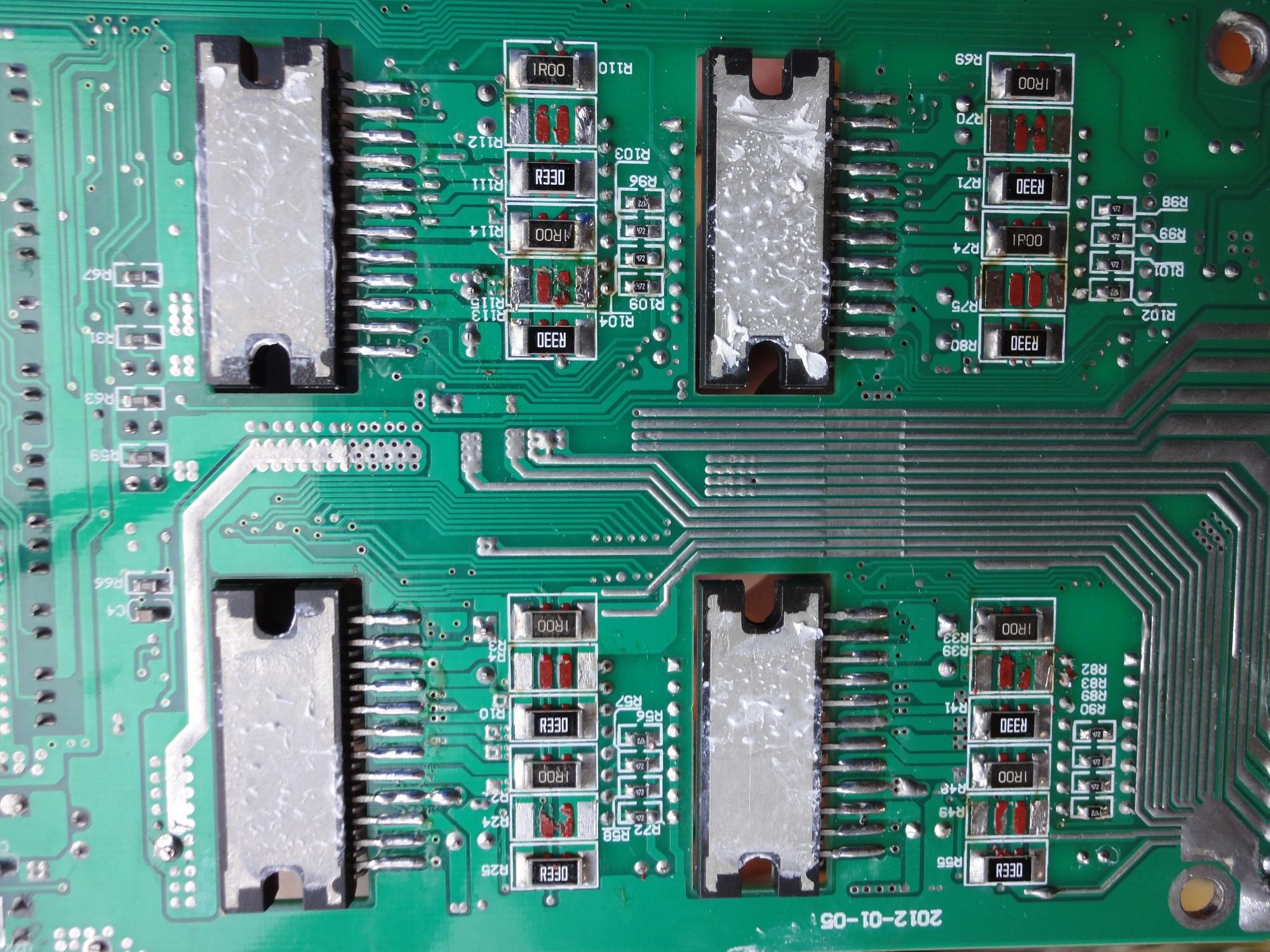
Ahora, si el controlador sólo tuviera las resistencias de 1Ω y 0.33Ω, esto daría una resistencia equivalente de 0.248Ω, lo que da una corriente máxima de 2.02A, suficientemente cerca de la especificación del motor. Así que sólo tengo que sacar las resistencias de 0.51 Ω y configurar el controlador al 100%.
Controlador de paso modificado para 2A
Alguien hizo un buen diseño con estas 3 resistencias en paralelo, se pueden configurar corrientes máximas de 0,5A, 1A, 1,5A, 2A ó 2,5A quitando 1 ó 2 resistencias.
I bought both a Sherline mill and a lathe a few years ago.
Sherline MillSherline Lathe
Right away I decided to add computer numerical control (CNC) by buying the hardware (stepper motors and mounts from Sherline) and save money by customizing the electronics.
Stepper Motor and Mount
There are some nice 3 and 4 axis stepper motor controllers available with the Toshiba TB6560AHQ chip, which is a PWM driver with microstepping capabilities and up to 3.5A capacity per phase. These controllers can be connected to a PC through a parallel port (which is preferred because of low latency) and cost less than 100 USD.
Stepper Controller
On a PC, LinuxCNC is an Ubuntu based Linux distribution (with an ISO installer) with real time extensions (needed to run the stepper motors smoothly) and CNC software to run G-code programs. It can be easily setup to use a parallel port stepper controller.
LinuxCNC
The original Sherline stepper motor is rated 2A and 3.2V. Most stepper motor controllers based on the Toshiba TB6560AHQ chip available in places like ebay are rated 3.5A but can be setup to 70%, 50% or 20%. So a 50% setup would give a would give me a 1.75A current level, which is close enough to the motor rating. Also a 24V and 8A power supply is enough to power the controller, a much higher voltage than the motor’s rating is needed to step it fast by forcing a current change in the motor’s coils at high voltage.
Anyway, by checking the Toshiba TB6560AHQ datasheet, I noticed that the maximum current level is defined by a couple of resistance (R) connected to pins 11 and 14 (one for each motor phase). The maximum current is set to 0.5V/R. These resistances have to withstand the maximum current at 0.5V, that means 1.75W for a 3.5A setup. They should be big enough for this power rating. By looking at my 4 axis controller circuit board, no big resistance are visible. So I disassemble the board (which has each driver screwed for power dissipation) and I looked on the lower side, finding 2 sets of 3 big resistances per driver.
Stepper controller current sensing resistances
These resistances seem to be in a parallel configuration and have values of 1Ω, 0.51Ω, and 0.33Ω. The equivalent resistance is then 0.167Ω, which means a 3A max current (my controller was documented to be rated 3.5A which seems not to be the case). The 50% configuration that I was considering would give me a 1.5A setup, much lower than the 2A motor rating.
Now, if the controller had only the 1Ω and the 0.33Ω resistances, that would be equivalent to 0.248Ω, which means a 2.02A max current, close enough to the motor rating. So I only have to remove the 0.51 Ω resistances and set the controller to 100%.
Stepper Controller modified for 2A max current
Somebody did a good design with these 3 resistances in parallel, you can setup a maximum current of 0.5A, 1A, 1.5A, 2A, or 2.5A by removing 1 or 2 resistances.