Después de hacer un poco de investigación. decidí configurar mi Prototipo de Driver Dynamixel con Teensy 3.2 para mi DARwIn-OP de forma de eliminar el código de retransmisión del loop:
void loop()
{
  if (Serial1.available())
  {
    uint8_t c = Serial1.read();
    Serial1.write(c);
  }
}
Este loop simplemente espera por un byte recibido por la UART y lo retransmite en la misma UART, la cual está configurada con un pin de dirección por hardware (RTS manejado por el transmisor).
Si pudiera usar el controlador DMA (Direct Memory Access) del Teensy para hacer la retransmisión, podría vaciar el código loop y utilizar el Teensy para otras tareas sin afectar el rendimiento de la retransmisión.
Los requerimientos para el DMA son bien simples:
Gatillar un requerimiento DMA cuando 1 byte es recibido por la UART.
La transferencia DMA tiene que ser de 1 byte.
La transferencia DMA debe leer desde el registro de DATA de la UART (data recibida).
La transferencia DMA debe escribir en el registro de DATA de la UART (para retransmisión).
No se tiene que involucrar la CPU en el proceso, no debe necesitarse eventos de interrupción o pooling.
Mirando a las capacidades del DMA de la CPU ARM MK20DX256VLH7 del Teensy, se ve factible, quedando operativo después de algunas pruebas.
Ahora la retransmisión tiene una latencia menor y un timing más parejo:
Teensy con UART manejada por DMA
Las señales en el gráfico son:
RX del Teensy (viene del TX del Odroid).
TX del Teensy.
Pin de Dirección por Hardward.
La codificación ahora tiene un setup más grande para configurar el DMA y la UART (la API serial del Teensy ya no es útil), pero la función loop() ahora está vacía:
#define UART_TXRTSE (2)
#define UART_TXRTSPOL (4)

#define BAUD_RATE (1000000)

void setup()
{
  int divisor = BAUD2DIV(BAUD_RATE);

  // DMA:

  // p 415 source address = uart data register
  DMA_TCD1_SADDR = &UART0_D;

  // p 415 source address offset
  DMA_TCD1_SOFF = 0;

  // p 416 transfer attributes: 8 bits
  DMA_TCD1_ATTR = 0;

  // p 417 minor byte count = 1 byte
  DMA_TCD1_NBYTES_MLNO = 1;

  // p 420 last source address adjustment = 0
  DMA_TCD1_SLAST = 0;

  // p 420 destination address = uart data register
  DMA_TCD1_DADDR = &UART0_D;

  // p 421 destination address offset
  DMA_TCD1_DOFF = 0;

  // p 423 channel link disabled
  DMA_TCD1_CITER_ELINKNO = 1;

  // p 423 last destination address adjustment = 0
  DMA_TCD1_DLASTSGA = 0;

  // p 427 channel link disabled
  DMA_TCD1_BITER_ELINKNO = 1;

  // p 424 control and status = 8 cycle stall, active
  DMA_TCD1_CSR = DMA_TCD_CSR_BWC(3) | DMA_TCD_CSR_ACTIVE;

  // p 402 enable DMA REQ channel 1.
  DMA_SERQ = DMA_SERQ_SERQ(1);

  // clock setup
  // p 252-259 system clock gating
  SIM_SCGC6 |= SIM_SCGC6_DMAMUX;
  SIM_SCGC7 |= SIM_SCGC7_DMA;
  SIM_SCGC4 |= SIM_SCGC4_UART0;

  // wait for clocks to become stable.
  delay(500);

  // p366 dma mux channel configuration
  DMAMUX0_CHCFG1 = DMAMUX_ENABLE | DMAMUX_SOURCE_UART0_RX;

  // UART:

  // p 1222 UART0 Control Register 5 request DMA on receiver full
  UART0_C5 = UART_C5_RDMAS;

  // RX TX pins
  CORE_PIN0_CONFIG = PORT_PCR_PE | PORT_PCR_PS |
                     PORT_PCR_PFE | PORT_PCR_MUX(3);

  CORE_PIN1_CONFIG = PORT_PCR_DSE | PORT_PCR_SRE |
                     PORT_PCR_MUX(3);

  // p 1208 uart0 baud rate
  UART0_BDH = (divisor >> 13) & 0x1F;
  UART0_BDL = (divisor >> 5) & 0xFF;
  UART0_C4 = divisor & 0x1F;

  UART0_C1 = UART_C1_ILT;
  UART0_TWFIFO = 2; // tx watermark
  UART0_RWFIFO = 1; // rx watermark
  UART0_PFIFO = UART_PFIFO_TXFE | UART_PFIFO_RXFE;

  UART0_C2 = UART_C2_TE | UART_C2_RE | UART_C2_RIE;

  // enable PIN 6 as hardware transmitter RTS with active HIGH.
  CORE_PIN6_CONFIG = PORT_PCR_MUX(3);
  UART0_MODEM = UART_TXRTSE | UART_TXRTSPOL;
}

void loop()
{
}
En realidad, por ahora ejecuto el típico ‘blink’ en la funcion loop() para saber que el Teensy está corriendo.
After doing some more research, I decided to jump into configuring my DARwIn-OP’s Dynamixel Teensy 3.2 Driver Prototype to get rid of the retransmitting loop code:
void loop()
{
  if (Serial1.available())
  {
    uint8_t c = Serial1.read();
    Serial1.write(c);
  }
}
This loop just wait for a byte received by the UART and retransmit it with the same UART, which is configured with a hardware direction pin (RTS driven by the transmitter).
If I could use Teensy’s DMA (Direct Memory Access) controller to do the UART retransmission, I could empty the loop so the Teensy can be used in any other tasks without affecting the retransmission performance.
The DMA requirement is very simple:
To trigger a DMA request when a byte is received by the UART.
The DMA transfer has to be 1 byte.
The DMA transfer has to read from the UART DATA register (received data).
The DMA transfer has to write into the UART DATA register (for retransmission).
Do not involve the CPU in the process, no interrupt events.
Looking at the DMA capabilities of the Teensy’s ARM MK20DX256VLH7 CPU, it looked feasible, and after a few tries I got it working.
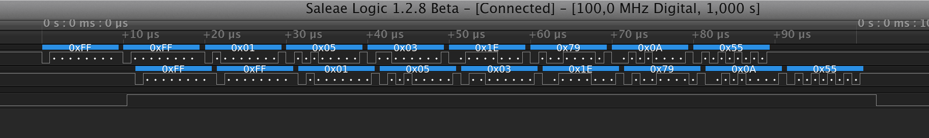
Now the retransmission has a smaller latency and a much smoother timing:
Teensy with UART managed by DMA
The signals in the chart are:
RX into the Teensy (from Odroid’s TX).
TX from the Teensy.
Hardward Direction Pin.
The coding has a larger setup to configure the DMA and the UART (Teensy’s interrupt driven serial API is no longer useful), but the loop() function is now empty:
#define UART_TXRTSE (2)
#define UART_TXRTSPOL (4)

#define BAUD_RATE (1000000)

void setup()
{
  int divisor = BAUD2DIV(BAUD_RATE);

  // DMA:

  // p 415 source address = uart data register
  DMA_TCD1_SADDR = &UART0_D;

  // p 415 source address offset
  DMA_TCD1_SOFF = 0;

  // p 416 transfer attributes: 8 bits
  DMA_TCD1_ATTR = 0;

  // p 417 minor byte count = 1 byte
  DMA_TCD1_NBYTES_MLNO = 1;

  // p 420 last source address adjustment = 0
  DMA_TCD1_SLAST = 0;

  // p 420 destination address = uart data register
  DMA_TCD1_DADDR = &UART0_D;

  // p 421 destination address offset
  DMA_TCD1_DOFF = 0;

  // p 423 channel link disabled
  DMA_TCD1_CITER_ELINKNO = 1;

  // p 423 last destination address adjustment = 0
  DMA_TCD1_DLASTSGA = 0;

  // p 427 channel link disabled
  DMA_TCD1_BITER_ELINKNO = 1;

  // p 424 control and status = 8 cycle stall, active
  DMA_TCD1_CSR = DMA_TCD_CSR_BWC(3) | DMA_TCD_CSR_ACTIVE;

  // p 402 enable DMA REQ channel 1.
  DMA_SERQ = DMA_SERQ_SERQ(1);

  // clock setup
  // p 252-259 system clock gating
  SIM_SCGC6 |= SIM_SCGC6_DMAMUX;
  SIM_SCGC7 |= SIM_SCGC7_DMA;
  SIM_SCGC4 |= SIM_SCGC4_UART0;

  // wait for clocks to become stable.
  delay(500);

  // p366 dma mux channel configuration
  DMAMUX0_CHCFG1 = DMAMUX_ENABLE | DMAMUX_SOURCE_UART0_RX;

  // UART:

  // p 1222 UART0 Control Register 5 request DMA on receiver full
  UART0_C5 = UART_C5_RDMAS;

  // RX TX pins
  CORE_PIN0_CONFIG = PORT_PCR_PE | PORT_PCR_PS |
                     PORT_PCR_PFE | PORT_PCR_MUX(3);

  CORE_PIN1_CONFIG = PORT_PCR_DSE | PORT_PCR_SRE |
                     PORT_PCR_MUX(3);

  // p 1208 uart0 baud rate
  UART0_BDH = (divisor >> 13) & 0x1F;
  UART0_BDL = (divisor >> 5) & 0xFF;
  UART0_C4 = divisor & 0x1F;

  UART0_C1 = UART_C1_ILT;
  UART0_TWFIFO = 2; // tx watermark
  UART0_RWFIFO = 1; // rx watermark
  UART0_PFIFO = UART_PFIFO_TXFE | UART_PFIFO_RXFE;

  UART0_C2 = UART_C2_TE | UART_C2_RE | UART_C2_RIE;

  // enable PIN 6 as hardware transmitter RTS with active HIGH.
  CORE_PIN6_CONFIG = PORT_PCR_MUX(3);
  UART0_MODEM = UART_TXRTSE | UART_TXRTSPOL;
}

void loop()
{
}
Actually, now I am running the typical ‘blink’ in the loop() function just so I know the Teensy is running.
Reemplacé my prototipo TTL inicial con un Teensy 3.2, éste es una placa de desarrollo con una CPU ARM de 32 bits y 72MHz en un formato pequeño de 35×18 mm.
Setup de Odroid-XU4, Teensy 3.2 y Servo MX-28
Seleccioné esta placa porque tiene varias interfaces seriales (UART) que soportan:
1 y 3 Mbps, velocidades que pueden ser usados con el servo MX-28.
Un pin de dirección por hardware. Su RTS por hardware puede indicar cuándo la UART está transmitiendo (al configurar que el RTS sea generado por el transmisor de la UART en vez del receptor de la UART), lamentablemente el Odroid-XU4 (como varias otras plataformas) no soporta esta opción por lo que he visto de la documentación disponible.
También el sitio web del Teensy se ve bastante bueno.
Robotis documenta este setup para conectar una UART al bus Dynamixel. Requiere una UART, un pin de dirección y lógica de 5V:
Interfaz de Robotis para Bus Dynamixel
Así, al poner el Teensy 3.2 entre el Odroid-XU4 y el bus Dynamixel, puedo generar el pin de dirección por hardware en vez de una implementación por software que puede tener problemas de timing.
Este es un esquema simplificado del setup, cambié el buffer de recepción por una puerta OR para evitar colocar una resistencia pull-up:
Esquemático Odroid-XU4, Teensy 3.2, Dynamixel
Este esquemático usa sólo una UART del Teensy. La función del Teensy es sólo retransmitir al bus Dynamixel y generar el pin de dirección. Mientras tando la señal de retorno del Bus va directo al Odroid, no hay necesidad de pasarla por el Teensy. De esta forma, este setup se puede usar con otros micro-controladores que sólo cuentan con 1 UART, además que no hay retardo extra en el retorno. El Odroid provee 1.8V y 5V que alimentan al Teensy y a los level shifters y el Teensy provee 3.3V que también alimenta a los level shifters.
Probablemente mi setup final use 2 UARTs del Teensy, de forma que éste pueda generar un retorno al Odroid y participe como otro dispositivo en el bus Dynamixel (siguiendo su protocolo) de forma que cumpla alguna función como PWM o I/O análogo. Dependerá de si sobra suficiente tiempo libre en el bus para agregar más comandos, que ya está bien limitado con los 8ms del ciclo de control del software de DARwIn-OP.
La Documentación para la UART del sitio de Teensy es bien clara y se programa con un add-on IDE de Arduino llamado Teensyduino.
El siguiente programa (que presenta problemas como se menciona luego) se deriva fácilmente de la documentación para retransmitir a través de la interfaz serial y con un pin de dirección:
void setup()
{
  Serial1.begin(1000000);
  Serial1.transmitterEnable(6);
}
void loop()
{
  if (Serial1.available())
  {
    uint8_t c = Serial1.read();
    Serial1.write(c);
  }
}
En este ejemplo, el pin 6 es configurado como pin de dirección para señalar cuándo hay una transmisión en proceso.
En el lado del Odroid-XU4, se puede usar la librería estándar de Dynamixel, sólo se necesita cambiar el nombre del dispositivo serial que corresponde a /dev/ttySAC0 para la UART del conector 10 expansión del Odroid.
Esta configuración con un servo MX-28 a 1Mbps funciona. Pero 2 cosas no funcionan como planificado:
Hay un retardo de como 5 bytes (50 us) en la retransmisión. Yo estaba esperando sobre 1 byte pero no tanto.
El pin de dirección 6 no funciona correctamente siempre (esto no se notó incialmente).
Retardo de Retransmisión
Retardo de Retransmisión en Teensy
La Documentación de la CPU MK20DX256VLH7 del Teensy describe en el capítulo 47 la interfaz UART. En la sección 47.3.21 describe el registro UART_RWFIFO que configura el umbral del buffer de recepción para notificar a la CPU vía interrupción, su valor es 1 después del reset.
Al revisar el código fuente de la librería Serial1.begin(), se ve que este umbral UART_RWFIFO es incremendado a 4. Esto permite bajar el uso de CPU al recibir data, pero agrega latencia. También, la librería maneja la UART vía interrupciones así que la CPU sabe que llega data sólo después de la recepción de los primeros 4 bytes (si se hubieran transmitido menos de 4 bytes también se notifica a la CPU por una interrupción de inactividad). La función Serial1.available() no interroga la UART, sino que revisa unos buffers en memoria que son llenados vía interrupciones.
Como estoy usando el Teensy sólo para retransmitir, bajé el umbral de vuelta a 1 byte modificando la función setup así:
void setup()
{
  Serial1.begin(1000000);
  Serial1.transmitterEnable(6);

  // set receiver buffer threshold for interrupt back to 1.
  uint8_t c2 = UART0_C2;
  UART0_C2 = c2 & ~UART_C2_RE; // disable C2[RE] (receiver enable)
  UART0_RWFIFO = 1;            // set receiver threshold
  UART0_C2 = c2;               // restore C2[RE]
}
void loop()
{
  if (Serial1.available())
  {
    uint8_t c = Serial1.read();
    Serial1.write(c);
  }
}
UART0_C2 y UART0_RWFIFO apuntan a los registros hardware de configuración y están definidos en las librerías de Teensy. La UART #0 de la CPU corresponde al objeto C++ Serial1.
Pin de Dirección con Falla
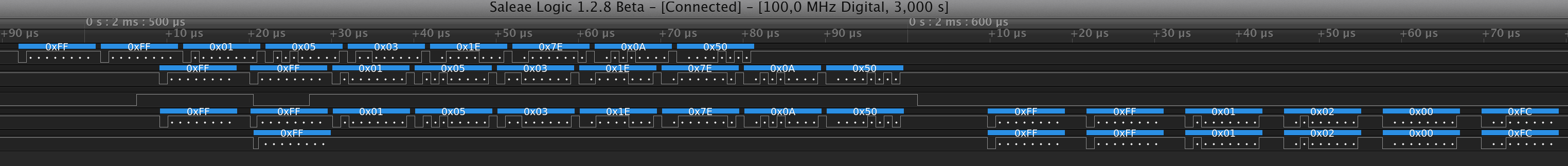
Después de hacer un test de estrés, 1 de cada 30 a 100 comandos al servo resultaban en un timeout esperando respuesta del servo. Después de varios intentos, logré capturar algunos casos de falla en la señal del pin de dirección:
Falla 1 Pin de Dirección – El servo responde, pero hay un byte de retorno inicial extra.Falla 2 Pin de Dirección – El servo recibe el byte #4 corrupto y no responde.
En los diagramas de captura digital, las señales son:
TX del Odroid-XU4
TX de retransmisión del Teensy 3.2
Pin de dirección del Teensy 3.2
Bus Dynamixel
RX de vuelta al Odroid-XU4
Normalmente, el pin de dirección funciona bien pero a veces se desactiva durante la transmisión. La falla 1 muestra un caso que no afecta al mensaje al servo, pero el Odroid recibe un byte 0xFF extra inicial. La falla 2 muestra un mensaje que se corrompe, el 4o byte en el bus dinamixel vale 63 pero debería valer 5.
Durante mi chequeo previo de la librería de Serial1, noté que la funcionalidad de transmitterEnable es implementada por software y no está usando la capacidad del RTS de hardware de la UART. Del análisis de señal se deduce que esta implementación por software no es correcta, como me interesa una solución por hardware, no intenté arreglar la librería, pero al menos noté un caso de carrera crítica no manejada apropiadamente.
Así que luego de revisar nuevamente la Documentación de la CPU ARM MK20DX256VLH7, encontré la solución por hardware en la sección 47.3.14, el registro de configuración UART_MODEM describe cómo configurar el RTS para indicar cuándo el transmisor de la UART está activo.
También, en este otro Documento ARM K20 se describe las múltiples configuraciones de pines de hardware. En el capítulo 8.1, lista cómo las diferentes señales internas de la CPU se pueden exponer en los pines externos. En particular, los pines de la CPU 25, 37 y 61 pueden ser configurados como RTS de la UART 0. Estos son pines de CPU y no de la placa Teensy. Este esquemático muestra que sólo 2 pines están disponibles en la placa: el pin 6 (corresponde al pin 61 de la CPU) y el pin 19 (pin 37 de la CPU). Después de buscar un poco más encontré ejemplos de código de cómo programar la configuración de un pin, en particular, el pin 6 para RTS (funcionalidad ALT3).
Esta es la versión final del setup que usa un pin de dirección por hardware, la llamada a la API Serial1.transmitterEnable() fue eliminada.
#define UART_TXRTSE (2)
#define UART_TXRTSPOL (4)

void setup()
{
  Serial1.begin(1000000);

  // set receiver buffer threshold for interrupt back to 1.
  uint8_t c2 = UART0_C2;
  UART0_C2 = c2 & ~UART_C2_RE; // disable C2[RE] (receiver enable)
  UART0_RWFIFO = 1;            // set receiver threshold
  UART0_C2 = c2;               // restore C2[RE]

  // enable PIN 6 as hardware transmitter RTS with active HIGH.
  CORE_PIN6_CONFIG = PORT_PCR_MUX(3);
  UART0_MODEM = UART_TXRTSE | UART_TXRTSPOL;
}
void loop()
{
  if (Serial1.available())
  {
    uint8_t c = Serial1.read();
    Serial1.write(c);
  }
}
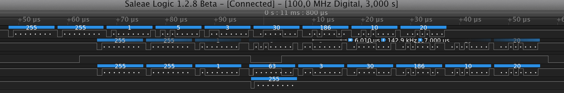
El pin de dirección funciona correctamente y tiene mejor consistiencia en los timings:
Driver Teensy funcionando bien
Ahora me falta reducir este prototipo a una placa debajo del Teensy 3.2.
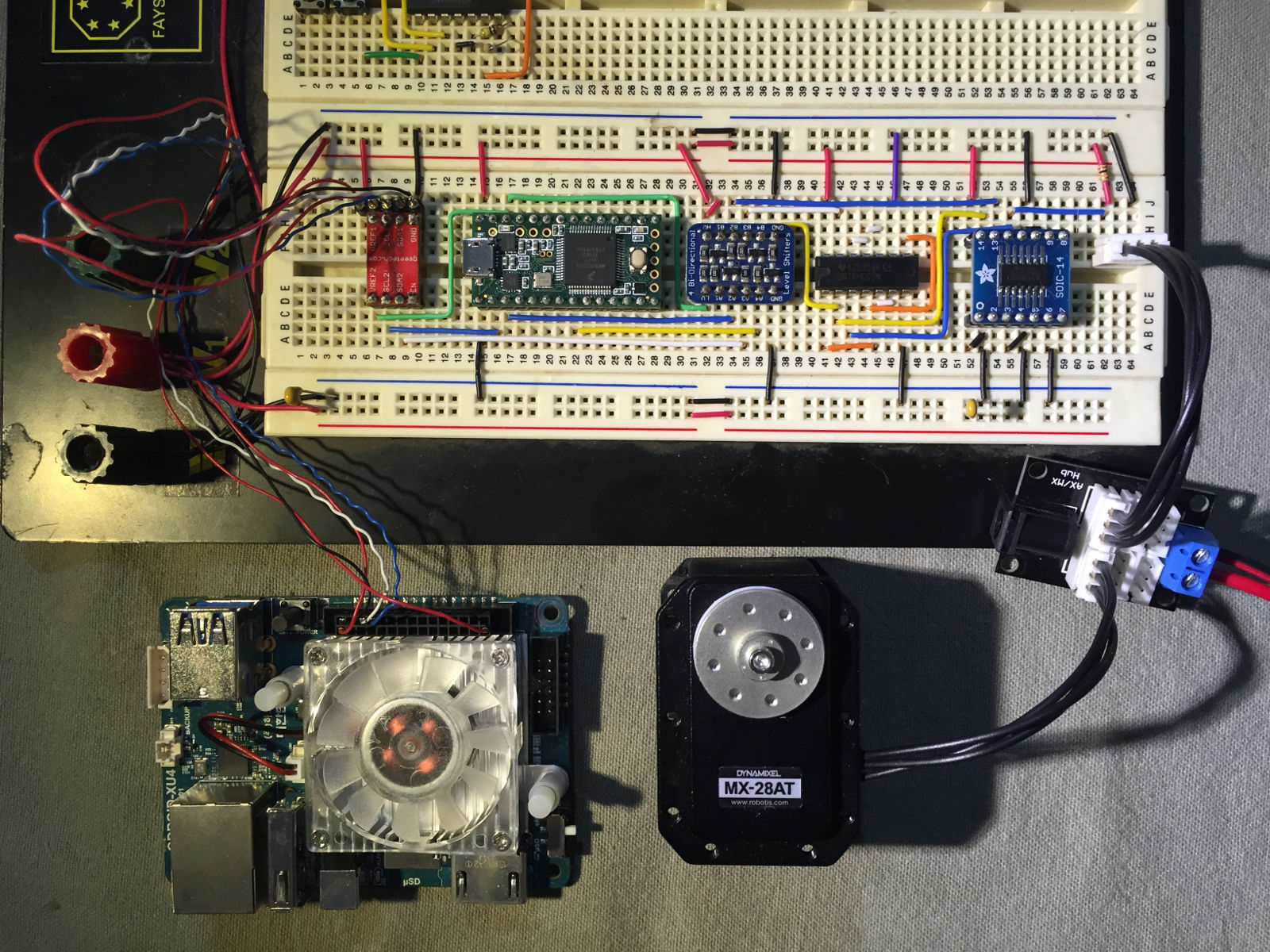
I replaced my initial TTL prototype with a Teensy 3.2, this is a development board with a 32 bit 72MHz ARM CPU in a small 35×18 mm board.
Odroid-XU4, Teensy 3.2 and Servo MX-28 Setup
I selected this board because it has several serial interfaces (UART) supporting:
1 an 3 Mbps, baudrates that can be used with the MX-28 servo.
A hardware direction pin. Its hardware RTS pins can signal when the UART is transmitting, (by configuring the RTS being driven by the transmitter instead of the receiver part of the UART, sadly the Odroid-XU4 (as several other boards) does not support this option from what I gather from its available CPU documentation.
Also Teensy’s site documentation seems good enough.
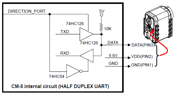
Robotis documents this setup to interface a UART to the Dynamixel bus. It requires a UART and a direction pin with 5V logic:
Robotis Citcuit Interface to Dynamixel Bus
So by placing a Teensy 3.2 between the Odroid-XU4 and the Dynamixel bus I can generate the direction pin by hardware instead of a delay-prone software implementation.
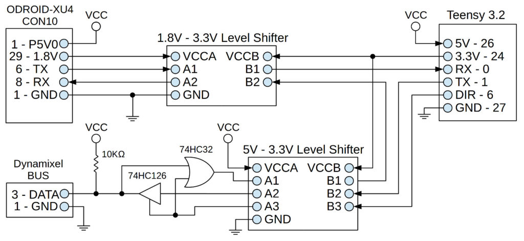
This is a simplified schematic of the setup, I changed the receive buffer with an OR gate in order to avoid a pull-up resistor:
Odroid-XU4, Teensy 3.2, Dynamixel Schematic
This setup only uses 1 UART on the Teensy. Teensy’s function is only to retransmit to the Dynamixel Bus and to generate the direction pin. Meanwhile the feedback from the Bus goes directly back to the Odroid, there is no need to pass it through the Teensy. This way, this setup can be used with other micro-controllers that only have 1 UART and there is no extra delay in the feedback. The Odroid provides 1.8V and 5V that power the Teensy and level shifters, and the Teensy provides 3.3V that also powers the level shifters.
Probably my final setup will use 2 UARTs in the Teensy, so it can generate a feedback to the Odroid and participate as another device in the Dynamixel bus (under its protocol) and have an extra function, like PWM or analog I/O. It will depend if there is enough idle time in the bus to add more commands, but the current 8ms control cycle in the DARwIn-OP software is very limited.
The Teensy’s site Documentation for the UART is strait forward. It is programmed with an add-on to the Arduino IDE called Teensyduino.
The following (and flawed, as pointed later) program is easily derived to retransmit through the serial interface with a direction pin:
void setup()
{
  Serial1.begin(1000000);
  Serial1.transmitterEnable(6);
}
void loop()
{
  if (Serial1.available())
  {
    uint8_t c = Serial1.read();
    Serial1.write(c);
  }
}
In this example pin 6 is setup as the direction pin to signal when a transmission is in progress.
On the Odroid-XU4 side, the standard Dynamixel library can be used. The only change it needs is the name of the serial device which is /dev/ttySAC0 for the UART exposed in the Odroid’s expansion connector 10.
This configuration at 1Mbps worked interacting with a MX-28 servo. But 2 things didn’t work as planned:
There was a delay of about 5 bytes (50 us) in the retransmission. I was expecting over 1 byte, but not that much.
The direction pin 6 did not work properly all the time (this was not noticeable right away).
Retransmission delay
Teensy Retransmission Delay
The Teensy’s ARM MK20DX256VLH7 CPU documentation describes in chapter 47 the UART interface. In section 47.3.21 it describes the UART_RWFIFO register that configures the threshold for the receive buffer before interrupting the CPU, its value is 1 after reset.
By checking the Serial1.begin() library source code I noticed that this UART_RWFIFO threshold is increased to 4. This allows for a lower CPU usage in handling receiving data, but it adds latency. Also, the library code handles the UART by hardware interrupt events. So actually the CPU knows that data was received after the first 4 bytes have being received (if less than 4 bytes is all that is transmitted, the CPU will also be notified by an idle interrupt event). The Serial1.available() function does not query the UART, it only checks some software buffers that are actually filled through interrupt handling.
Since now I am only using the Teensy to retransmit, I lowered the threshold back to 1 byte by modifying the setup function in my code:
void setup()
{
  Serial1.begin(1000000);
  Serial1.transmitterEnable(6);

  // set receiver buffer threshold for interrupt back to 1.
  uint8_t c2 = UART0_C2;
  UART0_C2 = c2 & ~UART_C2_RE; // disable C2[RE] (receiver enable)
  UART0_RWFIFO = 1;            // set receiver threshold
  UART0_C2 = c2;               // restore C2[RE]
}
void loop()
{
  if (Serial1.available())
  {
    uint8_t c = Serial1.read();
    Serial1.write(c);
  }
}
UART0_C2 and UART0_RWFIFO point to hardware configuration registers and are defined in Teensy’s library header files. The CPU’s hardware UART #0 maps to the library’s Serial1 C++ object.
Flawed Direction Pin
After stress testing, 1 in every 30 to 100 commands to the servo would result in a timeout waiting for the servo’s response. So after several attempts I captured some cases where the direction pin worked incorrectly.
Direction Pin Failure 1 – Servo still responds, but there is an extra initial return byte.Direction Pin Failure 2 – Servo gets byte 4 corrupted, no response.
In the digital probe chart, the signals are:
TX from Odroid-XU4
TX from Teensy 3.2 retransmission
Direction Pin from Teensy 3.2
Dynamixel Bus
RX back to Odroid-XU4
Normally, the direction pin works okay, but sometimes it would deactivate during transmission. Failure chart 1 shows a case that do not affect the message to the servo, but the Odroid receives back an extra initial 0xFF byte. Failure chart 2 shows a message being corrupted, the 4th byte in the Dynamixel bus has value 63 but should have value 5.
During my previous check at the Serial1 library source code I noticed that transmitterEnable functionality is actually implemented by software. It is not using the hardware RTS feature of the UART. From the signal analyzer probing, it is obvious that this software implementation is flawed. Since I am interested in a hardware solution, I did not try to fix the library source code, but I did notice at least one race condition not properly handled.
So after reviewing again Teensy’s ARM MK20DX256VLH7 CPU documentation, I found the hardware solution in section 47.3.14, the UART_MODEM configuration register describes how to configure RTS to signal when the UART transmitter is active.
Also this other ARM K20 document describes the hardware pins’ multiple configuration. In chapter 8.1, it lists how the different internal hardware signals can be multiplexed to the external CPU pins. In particular, CPU pins 25, 37, and 61 can be configured as RTS for UART 0. These are CPU pins, not Teensy’s board pins. This schematic shows that only 2 pins in Teensy’s board are available, pin 6 (connects to CPU pin 61) and pin 19 (connects to CPU pin 37). After digging a bit some other code around I found how to program the configuration of a pin, in particular, pin 6 as RTS (ALT3 functionality).
This is the final version for the setup to use a hardware controlled direction pin, the call to the flawed Serial1.transmitterEnable() library API was removed.
#define UART_TXRTSE (2)
#define UART_TXRTSPOL (4)

void setup()
{
  Serial1.begin(1000000);

  // set receiver buffer threshold for interrupt back to 1.
  uint8_t c2 = UART0_C2;
  UART0_C2 = c2 & ~UART_C2_RE; // disable C2[RE] (receiver enable)
  UART0_RWFIFO = 1;            // set receiver threshold
  UART0_C2 = c2;               // restore C2[RE]

  // enable PIN 6 as hardware transmitter RTS with active HIGH.
  CORE_PIN6_CONFIG = PORT_PCR_MUX(3);
  UART0_MODEM = UART_TXRTSE | UART_TXRTSPOL;
}
void loop()
{
  if (Serial1.available())
  {
    uint8_t c = Serial1.read();
    Serial1.write(c);
  }
}
The direction pin works flawlessly and has a more consistent timing:
Teensy Driver Working Fine
Now I need to shrink this prototype to a circuit board under the Teensy 3.2.
Como estoy usando un Odroid-XU3 (y pronto voy a actualizarlo con un Odroid-XU4) con un adaptador USB2AX para conectar los servos Dynamixel MX-28, me ha estado molestando el retardo USB del adaptador.
El USB2AX es un dispositivo USB 1.1 y el USB 1.1 tiene un entramado de 1ms para transmitir y recibir data. Cualquier
comando dynamixel toma al menos 2ms lo cual no es aceptable. Incluso usando los comandos bulk de lectura y escritura (los que toman incluso más tiempo en la medida que conecto más servos) me gustaría cumplir con el ciclo de control de 8ms del programa original del DARwIn-OP y me estoy acercando al límite.
Por suerte, como se describe en foro odroid, el UART del Odroid se puede configurar a la especificación del bus Dynamixel (8 bit, 1 stop, No Parity) a 1Mbps e incluso hasta 3Mbps!!!
Por lo que estoy trabajando en un driver para implementar la interfaz serial TTL half-duplex de Dynamixel con sólo los pines RX and TX del Odroid (sin usar ningún pin de control para comandar el half-duplex). De esta forma, se pueden usar UARTs simples como la que tiene el Odroid, que no tiene una salida por hardware para indicar una transmisión en proceso (y no quiero usar un gpio controlado por software para evitar errores de timing).
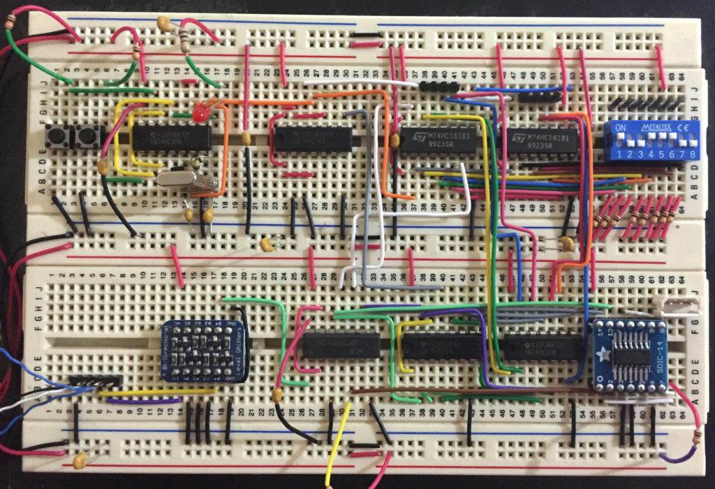
Por ahora hice un prototipo TTL (la UART del Odroid es de 1.8V, mientras que el bus Dynamixel es de 5V), pero voy a continuar reduciendo esto con un micro-controlador.
prototipo TTL de driver de servo
Antes de esto estaba trabajando en usar un UART SPI para reemplazar el USB2AX, pero eso se va a la basura ahora.
As I am using an Odroid-XU3 (and now I’ll be upgrading to an Odroid-XU4) with an USB2AX adapter to interface the Dynamixel MX-28 servos, I am getting annoyed by the USB delay of the adapter.
As the USB2AX is an USB 1.1 device and USB 1.1 has a 1ms time framing for transmitting and receiving data. Any Dynamixel commands takes at lease 2ms which is unacceptable. Even using bulk read and write instructions (which are taking longer time as I connect more servos) I would like to comply to the 8ms control loop in the original DARwIn-OP programming. So I am getting too close to the limit.
Luckily, as described in odroid forum, the Odroid’s UART interface can be setup to the Dynamixel’s bus specifications (8 bit, 1 stop, No Parity) at 1Mbps and all the way up to 3Mbps!!!
So I am working on a driver to implement the Dynamixel’s TTL half-duplex serial interface with just the RX and TX pins from the Odroid (without any control pin to command the half-duplex direction). This way it can be use with simple UARTs such as the one found on the Odroid which do not have a hardware output to signal an active transmission in progress (and I don’t want to use a software controlled gpio to avoid time mismatches).
So far I did a TTL prototype (Odroid’s UART is 1.8V while Dynamixel bus is 5V), but I’ll continue by shrinking this to a micro-controller soon.
TTL servo driver prototype
Before this I was working on using an SPI UART to replace the USB2AX, but that is going to the trash now.
Nuevamente después de otra pausa de verano estoy retomando este proyecto de mi clon de DARwIn-OP.
Actualmente estoy mejorando mi fresadora Sherline con comando digital de revoluciones y estoy reemplazando el tornillo del eje Y que ya está muy desgastado y empezó a notarse en los últimos cortes.
Again, after a summer pause I am retaking this DARwIn-OP cloning project.
Right now I am upgrading mi Sherline mill with digital RPM control and replacing the Y thread which was worn-out and it was getting visible in the last cuts.
Continuando con mi clon de robot DARwIn-OP, estoy cortando las piezas de los hombros.
Después de cortar la mayoría de las piezas del robot, estoy llegando a un mejor setup para cortes en mi fresadora CNC Sherline.
Primero empecé sujetando las planchas de aluminio sobre pequeñas placas de madera MDF, cortando con fresas de 3mm, una broca centro y varias brocas (1,6mm, 2,0mm, 2,05mm, 2,5mm y 2,6mm), después pasé a usar una fresa de 2.5mm para mejor acabado en los rebajes. Siguiendo el Manual de Fabricación de DARwIn-OP puse puntos de unión en los cortes finales de las piezas para que no se suelten. Después reemplacé el uso de una placa MDF de base por una de aluminio. Después probé fresar todo con sólo una fresa de 1.5mm, pero no me gustó el acabado y la calidad de los hoyos.
Ahora creo que tengo un mejor setup:
Siguiendo el setup de un amigo, reemplacé mi placa matriz de aluminio con una placa de MDF del mismo tamaño y sujeción.
Sujeto las planchas de aluminio con varios tornillos de 2.5mm x 10mm al rededor de la pieza a cortar. Para eso hago hoyos de 2mm x 9mm al MDF. Después de varios cortes, la placa de MDF puede ser reemplazada por otra.
Volví a usar una fresa de 2.5mm (o 2mm según la parte a cortar, aunque el manual de fabricación recomienda una fresa de 3mm, algunos diseños requieren cortes de radio 1mm).
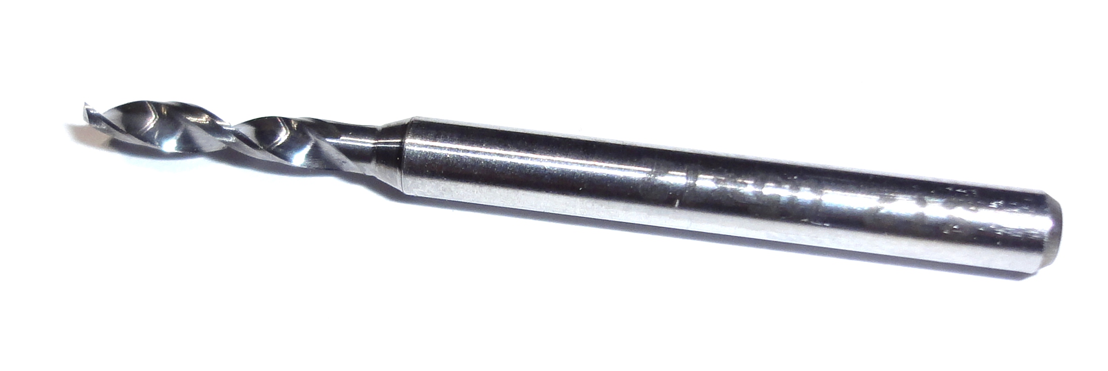
Volví a usar brocas de 1,6mm, 2,0mm, 2,05mm, 2,5mm y 2,6mm. Pero como uso ‘fresa brocas’ de carburo, ya no estoy usando la broca centro para marcar las perforaciones. (Después de varias pruebas no noté corrimiento en los hoyos).
Broca
Ya no estoy dejando puntos de unión en los cortes finales. Ahora atornillo la pieza al MDF antes del corte final usando varios de los hoyos originales de la pieza.
Para espacios grandes que deban ser vaciados dentro de una pieza, freso completamente el espacio para que no se desprendan pedazos de aluminio que puedan romper la fresa. Si el espacio es muy grande, entonces también lo atornillo para fresar menos.
También reemplacé el cabezal de mi fresadora Sherline con un modelo ER-16 (también de Sherline). Esto permite cambios de herramientas más fáciles y hay pinzas de sujeción (o collets) disponibles como las Techniks con muy buena precisión lo que es importante para mantener fresas pequeñas bien centradas.
Actualicé mi fresadora a 10k RPM (con un set de Sherline).
Con la fresa de 2.5mm estoy cortando a 5k RPM, 200mm/s de avance y 0.4 de profundidad de corte. Con la fresa de 2mm cambio la profundidad de corte a 0.25mm.
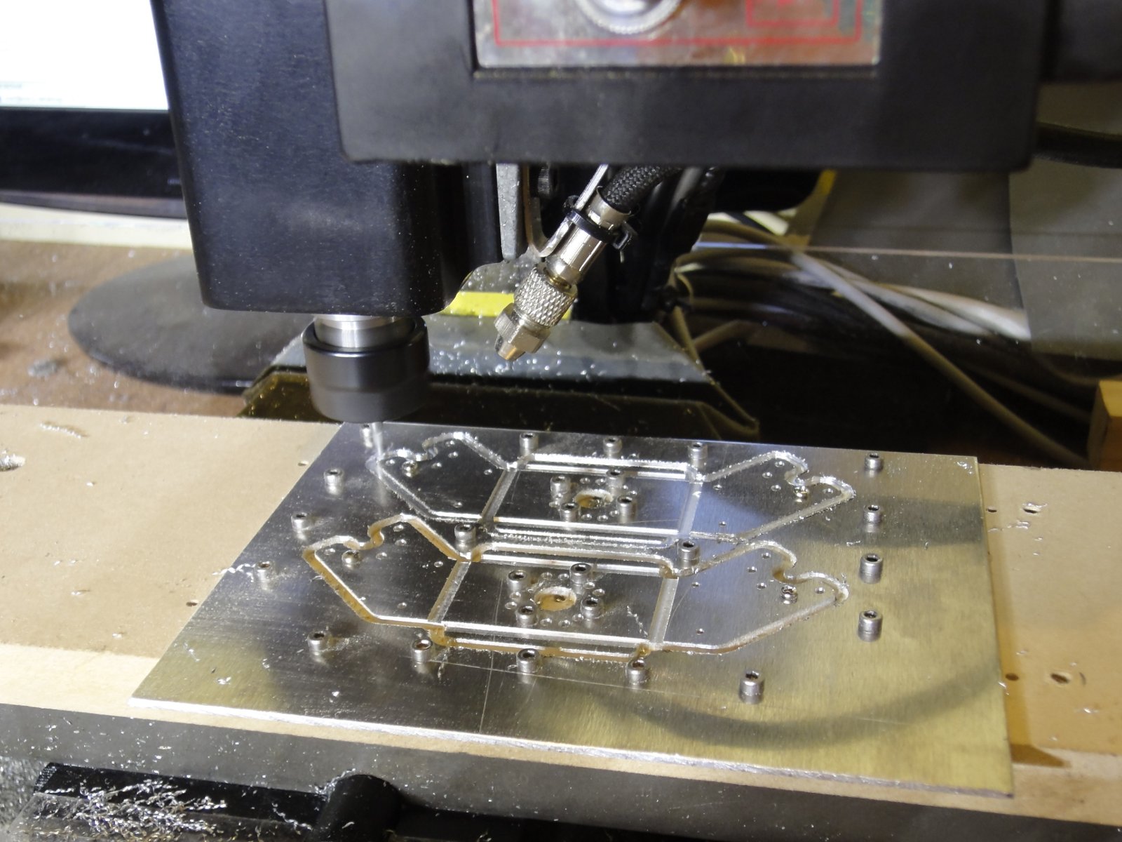
No uso lubricante, solamente un soplador de aire para mantener limpia el área de corte (ver foto).
La siguiente foto muestra el setup durante el último corte final:
Cortando los hombros del robot DARwIn-OP
Los archivos gcode más viejos que escribí no siguen estas reglas, pero no es difícil actualizarlos.
Continuing with my DARwIn-OP clone robot, I am now cutting the shoulder parts.
After most of the parts done, I am finally getting a better setup for cuts in my CNC Sherline mill.
First I started fixing the aluminum sheets over small MDF board, cutting with 3mm endmills, a center drill, and several drills (1.6mm, 2.0mm, 2.05mm, 2.5mm, and 2.6mm), later I moved to a smaller 2.5mm endmill for better score’s finish. Following the DARwIn-OP Fabrication Manual, I placed checks on the cutoff path so the parts would not come loose. Later I replaced the MDF base board with an aluminum plate. Then I tested only using a single 1.5mm endmill for everything, but I didn’t like the surface finish and the holes weren’t perfect enough.
Now I think I have a better setup:
Following a friend’s setup, I replaced my mill’s aluminum matrix plate with a MDF board with the same size and attachment.
I fix the aluminum plates to the MDF board with several 2.5mm x 10mm screws around the parts to be cut. For this, I drill the MDF with a 2mm drill, 9mm deep. After several cuts, the MDF can easily be changed with another one.
I went back to milling with a 2.5mm endmill (or 2mm endmill depending on the detail of the part, the Fabrication manual recommends a 3mm endmill, but some of the designs require 1mm radius cuts).
I went back to using drills of size 1.6mm, 2.0mm, 2.05mm, 2.5mm, and 2.6mm. But since these are carbide drills with a wider (1/8″) shaft, I am not using a center drill any more to mark the holes. (After a few tests, I saw no hole displacements).
Drill
I am not leaving checks on the cutoff paths anymore. Now I screw the part to the MDF before doing a complete cutoff. I use some of the original holes of the part for this.
For any big slot that need to be emptied on a part, I mill it completely so no sizable aluminum bit that gets loose could break the endmill. If the slot is too big, then I would also place some screws on it so I don’t have to mill it all off.
Also, I replaced the Sherline mill headstock with an ER-16 model (from Sherline also). This allows for much easier tool changes, and ER-16 collets are available such as Techniks collets with very good accuracy (low TIR) which is important to keep small endmills well centered.
I upgraded the mill to 10k RPM (with a 10k RPM pulley set from Sherline).
I am cutting with the 2.5mm endmill at 5k RPM, 200mm/s speed, and 0.4mm depth of cut. For the 2mm endmill, I change the depth of cut to 0.25mm.
I don’t use any lubricant, only an air blower to keep the cutting area clean (see photo).
The following picture shows the setup while milling the last cutoff:
Cutting DARwIn-OP shoulders
The older gcode files I wrote don’t follow this setup, but can easily be updated.